SLAAED8 October   2024 TAC5111 , TAC5112 , TAC5211 , TAC5212 , TAC5412-Q1 , TAD5112 , TAD5212


  1.   1
  2.   Abstract
  3.   Trademarks
  4. 1Introduction
  5. 2Signal Generator 1 (SG1)
    1. 2.1 Signal Generator 1 Introduction
    2. 2.2 Signal Generator 1 Amplitude and Output Channels
    3. 2.3 Signal Generator 1 Frequency
    4. 2.4 Generating Register Coefficients Using PPC3
  6. 3ADSR Envelope Parameters
    1. 3.1 ADSR Introduction
    2. 3.2 Restart and Sustain Timers
    3. 3.3 Attack, Release, and Decay Timers
    4. 3.4 Sustain Level
    5. 3.5 ADSR Envelope Example Script
    6. 3.6 Ultrasonic Activity Detection (UAD) ADSR Mode
  7. 4Signal Generator 2 (SG2)
    1. 4.1 Signal Generator 2 Introduction
    2. 4.2 Signal Generator 2 Amplitude
    3. 4.3 Signal Generator 2 Frequency
    4. 4.4 Signal Generator 2 Modes
      1. 4.4.1 Manual Mode
      2. 4.4.2 Continuous Pulse Mode
      3. 4.4.3 One Shot Mode
  8. 5Summary

Signal Generator 2 Modes

The following sections on SG2 modes describe how the ADSR envelope and SG2 generate different types of chirps. Parameters of the ADSR Envelope are discussed through these sections and in more details in Section 3.

Figure 4-3 shows how to access these modes in PPC3.
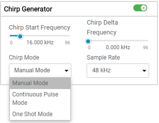
TAC5412QRGERQ1 SG2 Mode Selection GUIFigure 4-3 SG2 Mode Selection GUI