SLAAED8 October 2024 TAC5111 , TAC5112 , TAC5211 , TAC5212 , TAC5412-Q1 , TAD5112 , TAD5212
3.1 ADSR Introduction
ADSR stands for attack, decay, sustain, and release. The ADSR envelope is a commonly used in audio applications that require shaping sound. This feature has high precision and ultrasonic application modes. These parameters are applicable to SG2 pulses only.
Graphical Representation of High-Precision ADSR Envelope highlights the start and end point of each ADSR parameter. In the ADSR Envelope, Sustain level is between the attack and release time intervals. Attack time defines the positive ramp before the sustain level while the release time defines the negative ramp past the sustain level. Decay time controls the settling period after attack. This interval ends just before sustain level.
Across all these parameters are the Restart and Sustain timers. Restart Timer is always longer than Sustain timer.
32-bit registers configure each ADSR parameter. Registers B0_P28_R64 (0x40) to B0_P28_R67 (0x43) enable and disable the ADSR envelope. Refer to Programmable Register Map for 32-bit ADSR Parameters. This register map shows which SG2 modes require the ADSR note. Below is an example script template for ADSR note execution. Find ADSR note in use in this SG2 mode example script.
#ADSR example script template
#ADSR acknowledgement.
w a0 00 1c # locate ADSR note page
w a0 40 00 00 00 00 #acknowledge ADSR Envelope

#configure all other paramters next
w a0 xx xx
w a0 xx xx
#configure the output channel. Find this in the example script.

#Turn on ADSR envelope
w a0 00 1c # loacate ADSR note page
w a0 40 00 00 00 01 # turn on ADSR Envelope.
When building an I2C script, the ADSR enable_disable note is typically configured before other parameters as a 32-bit command, x00 00 00 00. This must be considered as an acknowledgment script to the envelope. After this, other ADSR scripts can be executed. Once all other ADSR parameters have been configured and all output channels enabled, this note is written as x00 00 00 01.
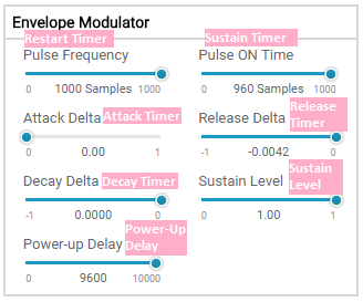
Figure 3-2 is the ADSR envelope PPC3 GUI.
 Figure 3-2 ADSR PPC3 GUI