SLAAED8 October 2024 TAC5111 , TAC5112 , TAC5211 , TAC5212 , TAC5412-Q1 , TAD5112 , TAD5212
2.4 Generating Register Coefficients Using PPC3
PPC3 is recommended to generate register values for all forms of tone generation configurations. This section uses SG1 amplitude and frequency configuration as an example to generate I2C scripts.
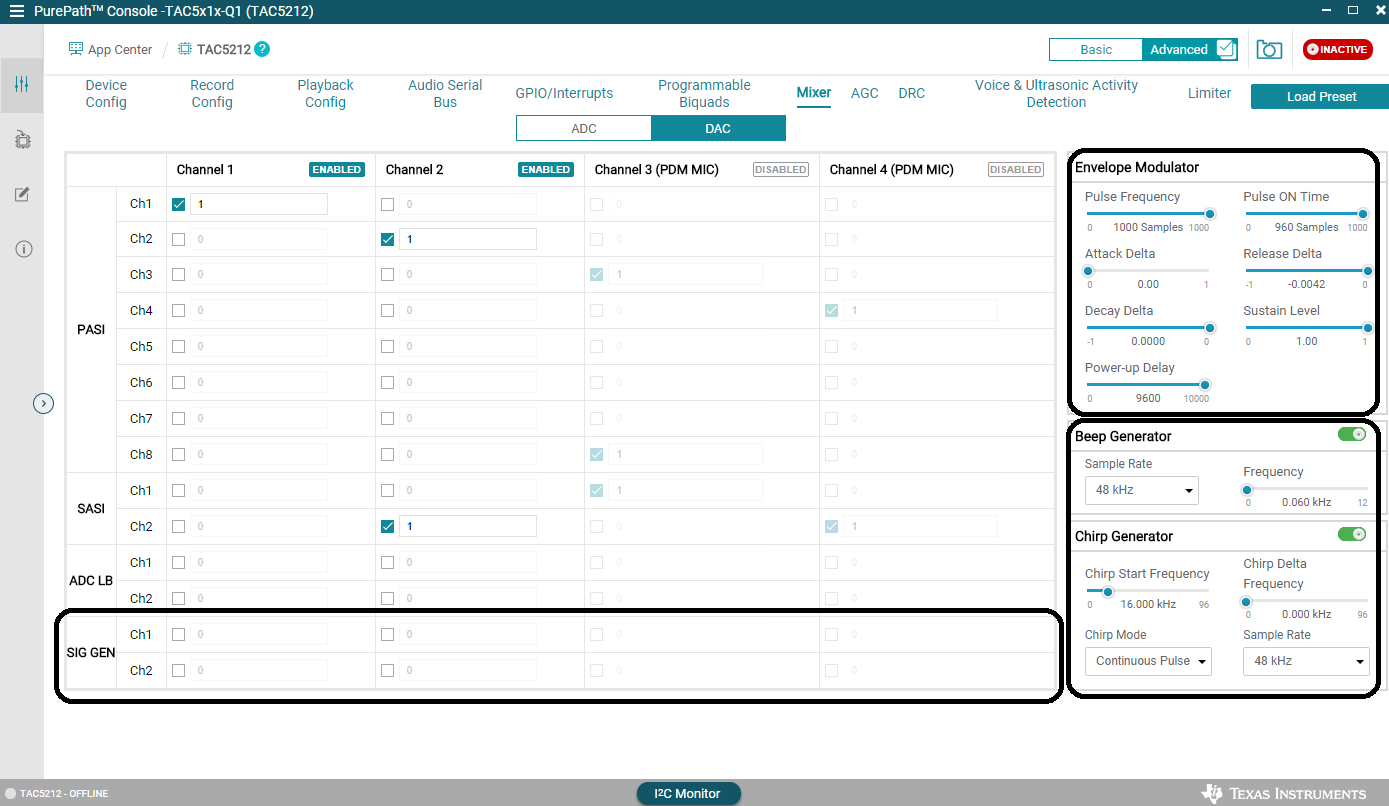
The mixing volume coefficient and this gain formula configure SG1 and SG2 amplitudes. Fill in coefficient values in the GUI boxes like Figure 2-2 suggests. This applies to all tone generators.
I2C script generation can be accessed offline in PPC3 without connecting a device to the software.
|
Instruction |
Image |
|---|---|
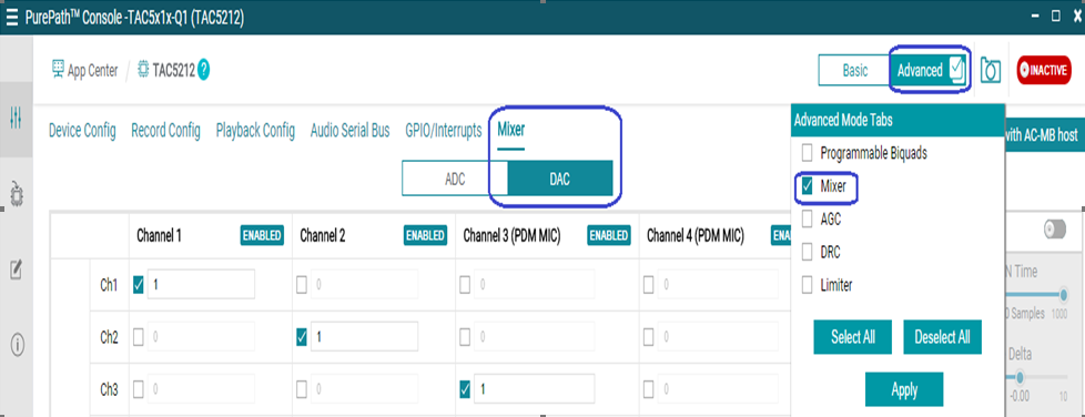
| Locate DAC Mixer Page in PPC3. |
 Figure 2-4 PPC3 step
1
 |
|
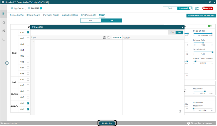
Open I2C Monitor Window. |
 Figure 2-5 PPC3 step
2
 |
|
Select LOG page. Click on green button. The button turns red. This means PPC3 is ready to record next I2C executions. |
 Figure 2-6 PPC3 step
3
 |
|
Return to main PPC3 window. Configure amplitude and frequency using GUI. Observe change in hex values on LOG window. |
 Figure 2-7 PPC3 step
4
 |