SLAAEE3A July 2023 – June 2024 MSPM0L1306
1 Introduction
There are different Gauge solutions based on MSPM0. Table 1-1 shows the quick compare between them for customers to choose the suitable one. This document focuses on introducing MSPM0 Gauge L1 solution.
Table 1-1 MSPM0 Gauge Solution Compare
| MSPM0 Gauge L1 | MSPM0 Gauge L2 | |
|---|---|---|
| Detected parameters | Voltage; Temperature | Voltage; Temperature; Current |
| Output key parameters | SOC | S0C; SOH; Remain capacity; Cycles |
| Used methods | Volt Gauge | Coulomb counting + Volt Gauge + Empty/Full compensation + Capacity learn |
| Suitable application | Output step data with low SOC accuracy | Output percentage data with high SOC accuracy |
Suitable battery type |
LiCO2/LiMn2O4 |
LiCO2/LiMn2O4/LiFePO4 |
The features of the level1 gauge solution based on MSPM0 are as shown:
- Work after MCU power-on without factory calibration or learning cycles.
- Support SOC (State of charge) and warning flag output.
- Low requirement for battery chemistry parameters input.
- Total solution takes about 6K flash and 1.6K SRAM.
- Current consumption without UART communication (NO_OUTPUT mode) is about 3 µA.
The solution is combined of three parts. All of them can be found at MSPM0 Gauge L1 Development package.
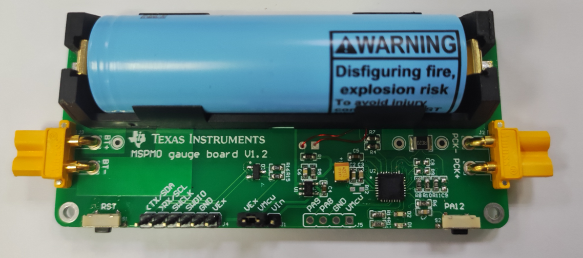
- The hardware board is used to evaluate the
total solution with MSPM0L130x integrated.
 Figure 1-1 MSPM0 Gauge Hardware Board
 - The software
project based on MSPM0L130x, including the used gauge algorithm.
 Figure 1-2 MSPM0 Gauge Software Project
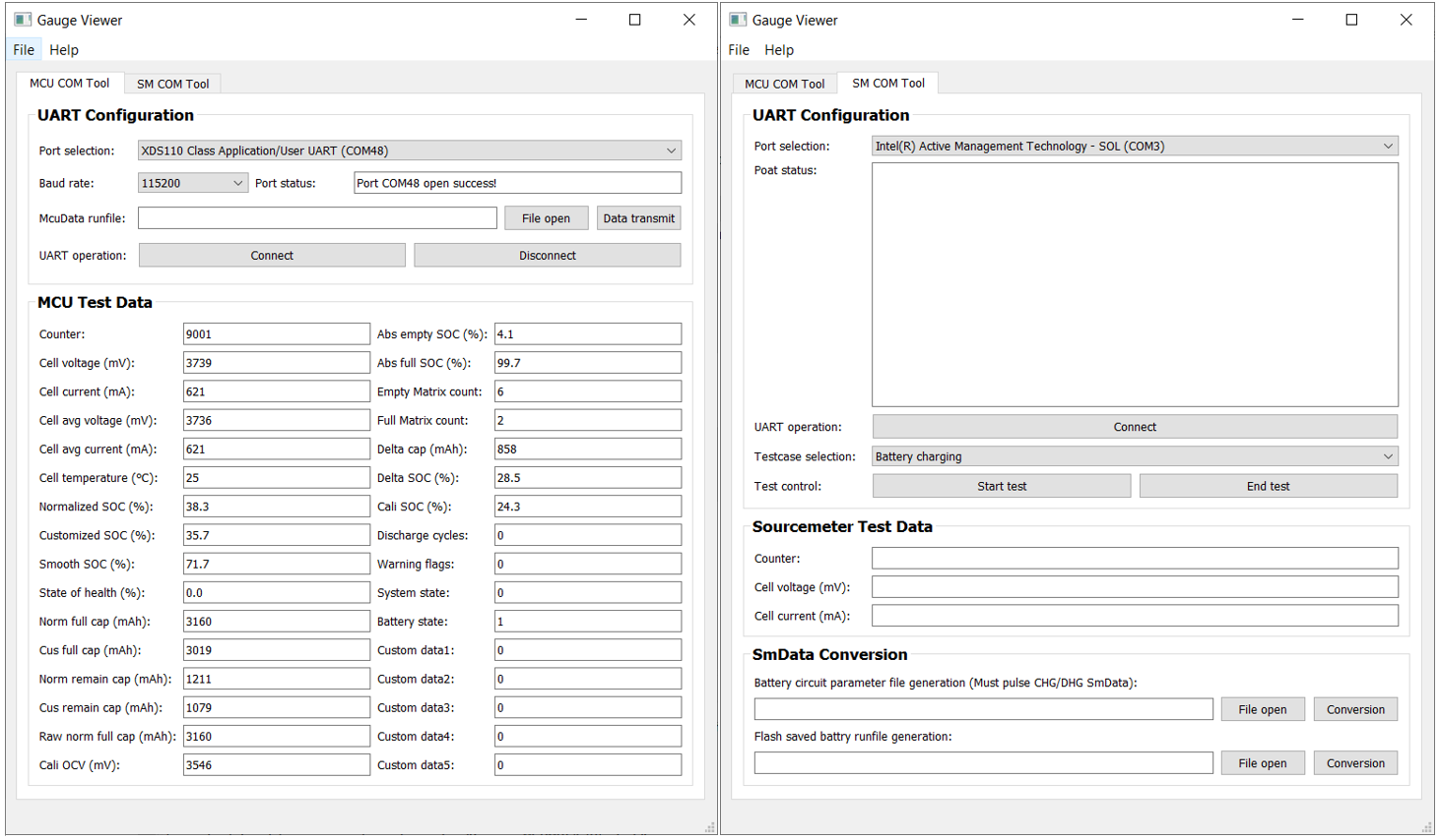
 - The GUI is written with Python®, which can be used to communicate with the gauge board, run test pattern by
controlling a source meter and generate battery parameters.
 Figure 1-3 MSPM0 Gauge GUI Project