SLAAEE3A July 2023 – June 2024 MSPM0L1306
3.2 Gauge GUI Introduction
Gauge GUI is also a important part of this design and can be used for recording MCU data, running battery test case, and do data conversion. This GUI has two pages. First is MCU COM Tool, used to communicate with MSPM0 and record the MCU transmitted battery running data. Second is SM COM Tool, used to communicate with the source meter, run battery test case and record the test data sent from the source meter. Data conversion is also done in this page to pair with the different gauge working mode.
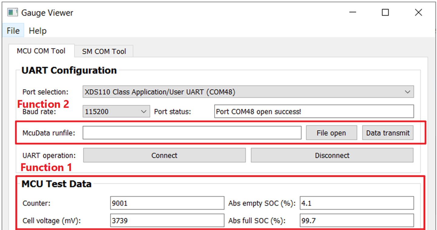
First, observe the MCU COM Tool with two functions shown in Figure 3-4. The first function is to receive the battery running data from MCU. The data is saved automatically in Microsoft® Excel® with a name “time-McuData.xlsx”, after the test is finished or you stop the test.
The second function is to load the selected “time-McuData.xlsx” Excel file and transmit the cell current, cell voltage and cell temperature data in this file to MCU for algorithm running, paired with the related gauge mode (Communication data input mode).
 Figure 3-4 MCU COM Tool functions
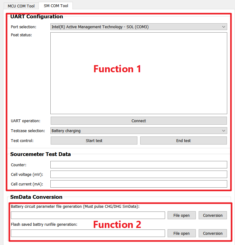
The SM COM Tool has two functions, shown in Figure 3-5. Function 1 is used to control the source meter to run the battery test case. Then show and record the data measured by source meter. The record data is saved in Excel with a name “time-SmData.xlsx”. If you want to recreate this part, for software, you need to at least install NI_VISA. For hardware, buy a USB-to-rs232 wire and a Keithley® 2602A source meter.
Function2 helps to converge the record data into C files. “Battery circuit parameter file generation” is used to extract the battery parameters, including SOC, OCV and Rcell from a pulse CHG/DHG file, to generate the “circuitParamsTable”. “Flash saved battery runfile generation”, is used to converge the record file into a C file. Then you can save the file into MCU for running, paired with the related gauge mode (Flash data input mode).
 Figure 3-5 SM COM Tool function
A Gauge GUI execution file is supplied; you can use the file for evaluation without installing python. However, if you want to customize the battery test cases under the SM COM Tool, TI recommends that you to use the source code. See the next section for more details about how to use the GUI.