SLAAEF8 January   2024 MSPM0L1105 , MSPM0L1105


  1.   1
  2.   Abstract
  3.   Trademarks
  4. 1Introduction
  5. 2Function Explanation
  6. 3Single Wire UART
    1. 3.1 Background
  7. 4Power and Communication Logic
  8. 5Software
    1. 5.1 Overall Flowchart
    2. 5.2 IOMUX
    3. 5.3 Power/Communication Software Design
    4. 5.4 Other Resources
  9. 6Hardware
    1. 6.1 Test Results
  10. 7References

Hardware

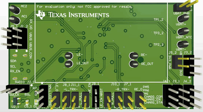
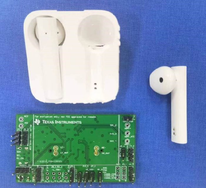
The PCB design and final prototype can be seen in Figure 6-1.

GUID-20230912-SS0I-BN8K-CGGT-4TTR691K6CKB-low.png GUID-20230912-SS0I-HGVK-HNN8-GXD2QDGPTP2Z-low.png GUID-20230912-SS0I-HB8V-HR00-BNJC9ZT9GVXF-low.jpg GUID-20230912-SS0I-PWCP-NPQM-CF4HX9VKJCMQ-low.jpg Figure 6-1 PCB Design and Final Prototype

The PCB is designed so that it can be perfectly fit with a third-party TWS cradle.