SLAAEH3 December 2023 MSPM0G3507
In modern society, cars are already the most commonly used means of transportation for humans. The Heating, Ventilation and Air Conditioning (HVAC) is an indispensable and important part of the car, which uses heating or cooling to keep the ambient temperature in the car within a comfortable range, which improves the passenger experience.
Depending on the vehicle type, HVAC systems vary in complexity and degree of automation. A simple HVAC uses physical knobs and dials to control the ambient temperature and wind speed. Complex HVACs automatically control ambient temperature, humidity, and air quality with several sensors, as Figure 1 shows.
 Figure 1 Smarter HVAC Control
Panel
Figure 1 Smarter HVAC Control
PanelHVAC system overview
The HVAC system is composed of a blower, compressor, evaporator, heater, sensor, air duct, and air valve. The function of an HVAC system is to exchange air, and change temperature, humidity, and air quality when exchanging air. The air that is exchanged comes from the blower, and is controlled by the air valve to extract air from inside or outside the car. The blower sends the air to the evaporator to decrease the temperature and to the heater to increase the temperature.
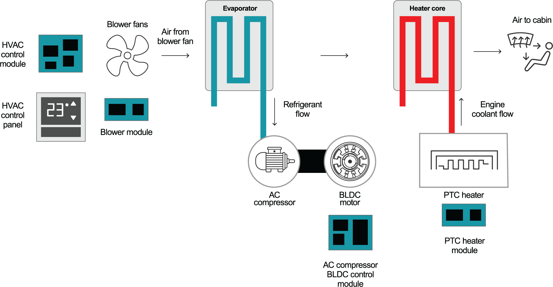
In the traditional internal combustion engine (ICE) vehicles, the heat source comes from the ICE. The air duct and valve are used to control the proportion of low-temperature and high-temperature air, which can control the temperature of the air sent to the car, and as a result, control the ambient temperature in the car. While in hybrid electric vehicles (HEV) and electric vehicles (EV), there is an interior PTC heater module in the system that heats the air. Figure 2 shows the heating and cooling system in a HEV/EV.
 Figure 2 Heating and Cooling System in
a HEV/EV
Figure 2 Heating and Cooling System in
a HEV/EVHVAC fan control module
HVAC fan control is distributed among multiple actuators in the HVAC system. In the blower, controlling the air intake volume of the HVAC system by controlling the speed of the fan is required. In the evaporator, a fan is required to generate additional air flow to assist in completing the heat exchange between the air and the cold core of the evaporator. Automotive HVAC fan control module designs require:
- Reduced EMI to optimize system performance.
- Scalable power and communication interfaces.
- Comprehensive diagnostics for fault identification and protection.
- High speed with wider speed range, high torque and low noise
Figure 3 shows the basic system block diagram of the automotive HVAC fan control module.
 Figure 3 HVAC Fan Control Module System
Block Diagram
Figure 3 HVAC Fan Control Module System
Block DiagramTI’s scalable MSPM0 MCU portfolio features an Arm® Cortex® -M0+ core, with a maximum CPU speed of 80 MHz, and the pin-to-pin compatible portfolio covers 4 KB to 512 KB of flash memory with optional analog integration, multiple timer resources, and LIN and CAN-FD interfaces for automotive applications. This provides a low-power, high-performance design for HVAC fan control module design. Figure 4 shows an example.
 Figure 4 MSPM0 Platform Features and
Advantages
Figure 4 MSPM0 Platform Features and
AdvantagesMSPM0 design for HVAC fan control module
Figure 5 shows the proposed block diagram of an MSPM0G350x-based HVAC fan control design.
 Figure 5 MSPM0 Platform Block Diagram
for HVAC Fan Control
Figure 5 MSPM0 Platform Block Diagram
for HVAC Fan ControlKey features of MSPM0G350x in the following applications:
- Math accelerator for higher data processing capabilities (division, trigonometric, square)
- Advanced timers for complementary PWM with dead-band support
- Dual 12-bit SAR ADCs with 11.2 ENOB and 4-Msps sampling rate
- Internally used 8-bit DACs and 1-Msps 12-bit buffer DAC
- Two on-chip zero-drift chopper op-amps (OPA) and one general purpose amplifier
- Three high speed comparators for protection
- LIN or CAN-FD interface
Resources
Order a MSPM0 LaunchPad™ development kit LP-MSPM0G3507 now to start evaluating MSPM0 for HVAC fan control. Jump-start coding with the software development kit (SDK) MSPM0-SDK, and graphical code generation tool SysConfig. The following links provide additional resources.
- MSPM0 overview page
- MSPM0 Academy
- MSPM0 LaunchPad development kits
and resources:
- LP-MSPM0L1306 LaunchPad development kit
- Texas Instruments, MSPM0 L-Series MCUs Hardware Development Guide , application note.
- LP-MSPM0G 1507 LaunchPad development kit
- Texas Instruments, MSPM0 G-Series MCUs Hardware Development Guide, application note.