SLAAEI4 August 2024 TAC5111-Q1 , TAC5212-Q1 , TAC5311-Q1 , TAC5312-Q1 , TAC5411-Q1 , TAC5412-Q1 , TAD5212-Q1
3.2 Limiter Response
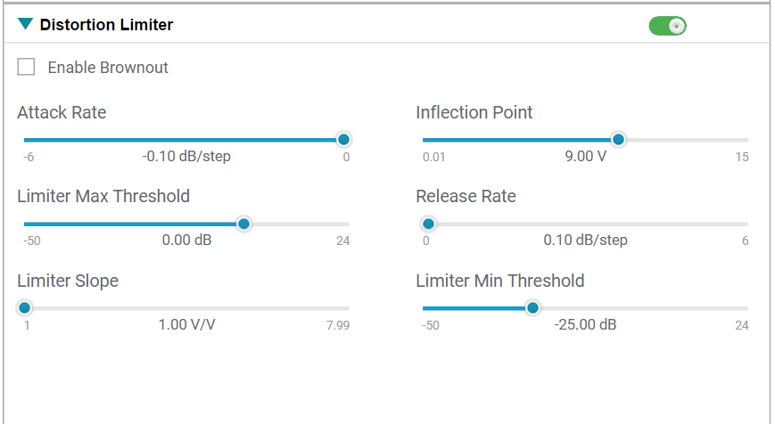
The settings for the Distortion Limiter validation, shown in Figure 3-3, can be programmed through direct I2C communication and are configurable in the PurePath™ Console 3 software.
 Figure 3-3 Distortion Limiter PPC3
Configuration
Figure 3-3 Distortion Limiter PPC3
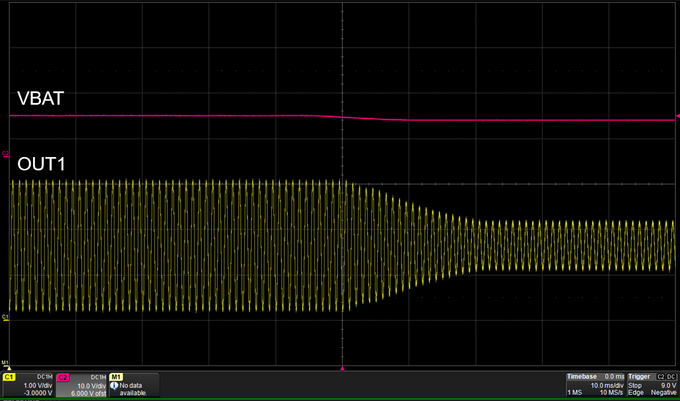
ConfigurationAn example of the limiter actively adjusting the gain is represented in the scope capture of Figure 3-4. In this example, VBAT, provided by a bench top supply and represented on Channel two is ramped down over time causing the limiter to engage. Prior to the inflection point, the output signal on Channel one is a full-scale 2Vrms signal attenuated to approximately 120mVrms as VBAT drops.
 Figure 3-4 Distortion Limiter Attack
Profile
Figure 3-4 Distortion Limiter Attack
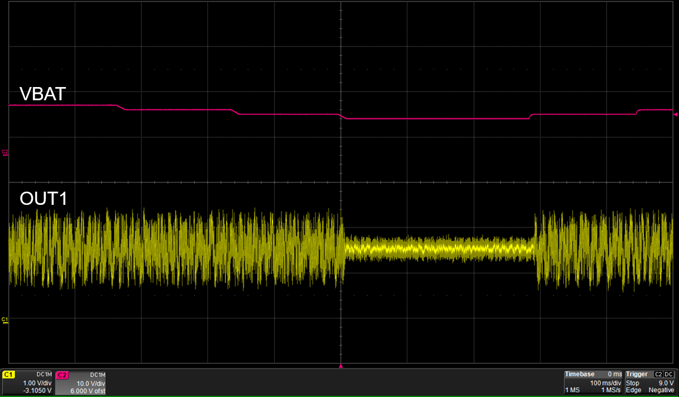
ProfileFigure 3-5 is an example of the attack and release rate of the limiter engaging as VBAT drops and suddenly ramps back to a level above the inflection point.
 Figure 3-5 Distortion Limiter Two-Stage
Response