SLAAEL6 September 2024 MSPM0G3507
2 Hardware Setup
This section describes the differences in the hardware setup compared to the description in each of the device-specific EVM User's Guides. Check the hardware setup in:
- Tool pages:
- Documentation:
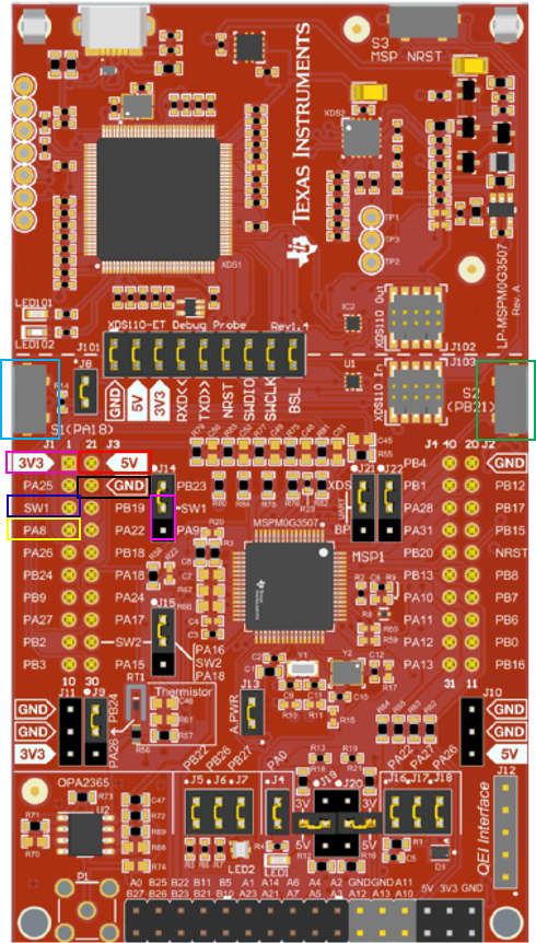
The sample code replaces the USB2ANY with the LP-MSPM0G3507. There are two methods to connect the LP-MSPM0G3507 to the TPS929xxxEVM, the TPS929240EVM is used for demonstration here.
Both connection methods are listed in Table 2-1. The locations on the LP-MSPM0G3507 are shown in Figure 2-1. Firstly, jump the SW1 and PA9 of J14 together. Besides the connections, the switches S1 (cyan) and S2 (green) of the LP-MSPM0G3507are used in the sample code that is described in more detail in Section 4.1. On the TPS929xxxEVM, the jumpers have to be set correctly for each mode. This is described in the device-specific EVM User's Guides.
| Interface | Board | UART-RX | UART-TX | +3.3V | GND | +5V |
|---|---|---|---|---|---|---|
| LP-MSPM0G3507 | PA9 | PA8 | J1-1 | J1-22 | J1-21 | |
| CAN | TPS929120CANEVM | J3-13 | J3-14 | J3-15 | J3-16 | +5V (J3-21) |
| UART | TPS929120EVM | J3-3 | J3-4 | J3-5 | J3-6 | \ |
| TPS929160EVM | J29-3 | J29-4 | J29-5 | J29-6 | \ | |
| TPS929240EVM | J4-3 | J4-4 | J4-5 | J4-6 | \ |
 Figure 2-1 Connections on
LP-MSPM0G3507