SLAAEM0 June 2024 MSPM0C1104 , MSPM0C1104 , MSPM0L1105 , MSPM0L1105 , PGA460 , PGA460
2 Hardware Introduction
To evaluate the solution based on PGA460 and MSPM01104, the following hardware elements are required:
- BOOSTXL-PGA460 (PGA460-Q1 ultrasonic sensor signal conditioning evaluation module with transducers)
- LP-MSPM0C1104 (MSPMC1104 LaunchPad™ development kit for 24-MHz Arm® Cortex®-M0+ MCU)
- A computer with Windows® 7 or later, and .NET Framework 4.5
- Micro-USB to USB cable (included with the purchase of LP-MSPM0C1104)
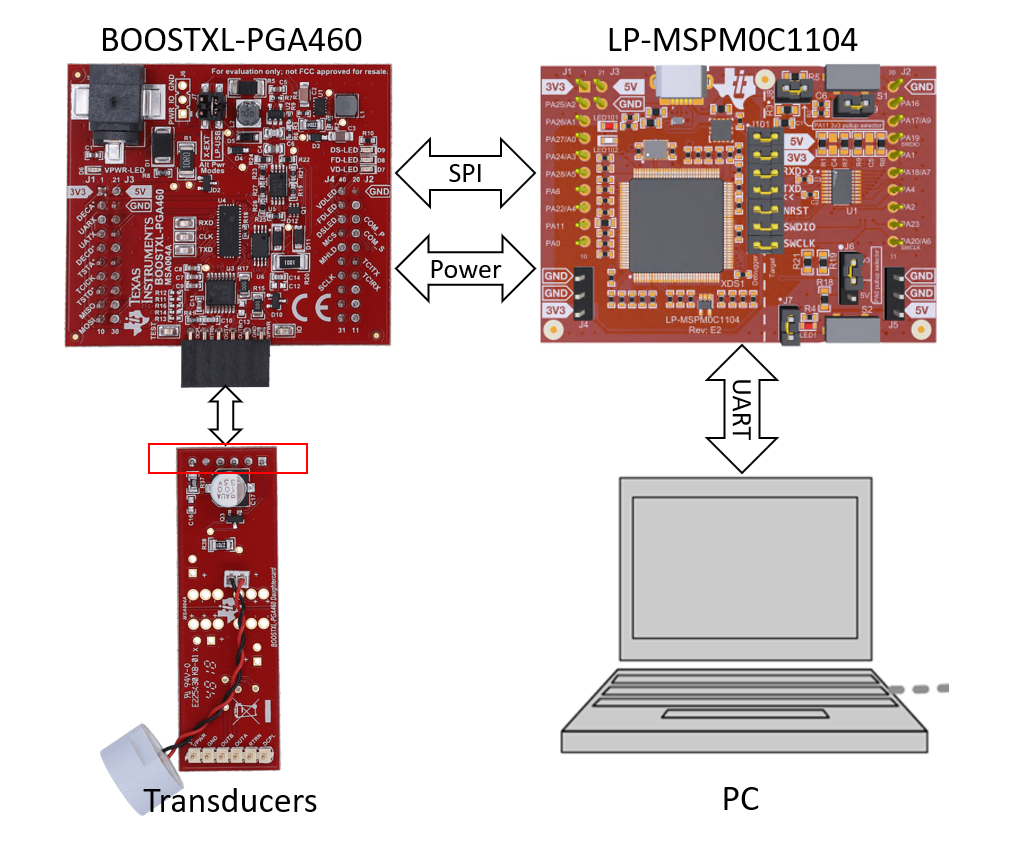
In the solution, MSPM0C1104 acts as the main controller to configure PGA460 via SPI, and sends the measurement results to PC via universal/asynchronous receiver/transmitter (UART). Figure 2-1 shows the simply system block diagram.
 Figure 2-1 System Block Diagram
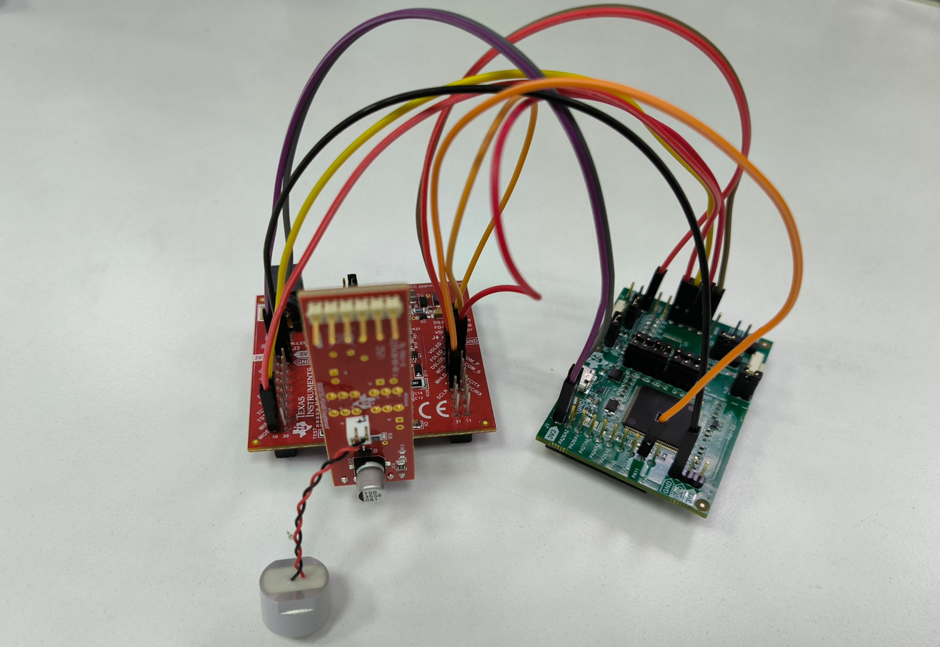
PGA460-Q1 support multiple communication interfaces, including USART, TCI, SPI and One-Wire UART. USART Synchronous Mode is identical to a SPI without a chip select because the addressing is handled by the three-bit UART_ADDR value to enable up to eight device son a single bus. In this solution, the three-wire SPI communication interface was used on MSPM0C1104 to control PGA460. To enable SPI communication module in PGA460, pull down P18(COM_P) and pull up P17(COM_S), P37(MHLD), P36(MCS) on PGA460. This is realized by controlling PA2, PA17 and PA23 on MSPM0C1104. The power supply (5V, 3V3, GND) and SPI (MOSI, MISO, Clock) can be connected correspondingly. All the hardware connection between PGA460 EVM and LP-MSPM0C1104 is shown in Table 2-1.
| Connection Type | Connection Name | LP-MSPM0C1104 Pin Number: Pin Name | BOOSTXL-PGA460 Pin Number: Pin Name |
|---|---|---|---|
| SPI | SPI: MOSI | PA18: SPI_PICO | P10: MOSI |
| SPI: MISO | PA4: SPI_POCI | P9: MISO | |
| SPI: Clock | PA11 | P34: SCLK_LP | |
| SPI enable | COM_PD | GND | P18: COM_P |
| COM_SEL | PA2 | P17: COM_S | |
| MEM_HOLD | PA17 | P36: MHLD | |
| MEM_CS | PA23 | P37: MCS | |
| Power connections | Power: 3.3V | J1:3V3 | P1: 3V3 |
| Power: 5V | J3:5V | P21: 5V | |
| Power: Ground | GND | P22: GND |
The final setup is shown in Figure 2-2.
 Figure 2-2 Hardware Setup