SLAAEM0 June 2024 MSPM0C1104 , MSPM0C1104 , MSPM0L1105 , MSPM0L1105 , PGA460 , PGA460
3.1 MCU Initialization
The first step of the high-level software flowchart is MCU initialization. For this step, use sysconfig, which can set peripherals parameters and initialize the MCU conveniently and efficiently.
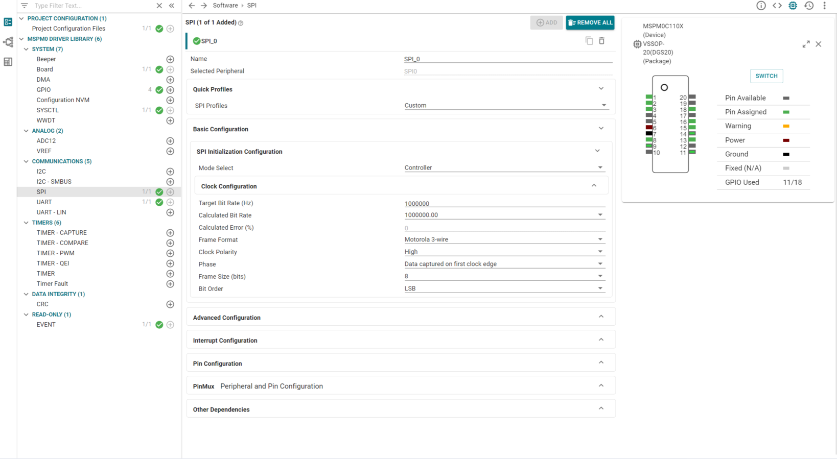
Using the SPI configuration as an example, the SPI terminals of the master controller must be adapted to the PGA460-compatible format and baud rate. Select controller mode in this solution, and specify the master controller clock is referenced to a source and frequency that can support the designated baud rate. In this solution, set baud rate as 1MHz, and customers can make an adjustment within reasonable limits. As for frame format, the MCU configuration must meet the requirements of the PGA460, which use Motorola 3 wire frame format. The clock polarity is high (SPO = 1), and data captured on the first clock edge transition (SPH = 0). Frame size is 8 bits, and bit order is LSB first. These parameters can be easily configured in the sysconfig as shown in Figure 3-3.
 Figure 3-3 SPI Configuration in
Sysconfig
Figure 3-3 SPI Configuration in
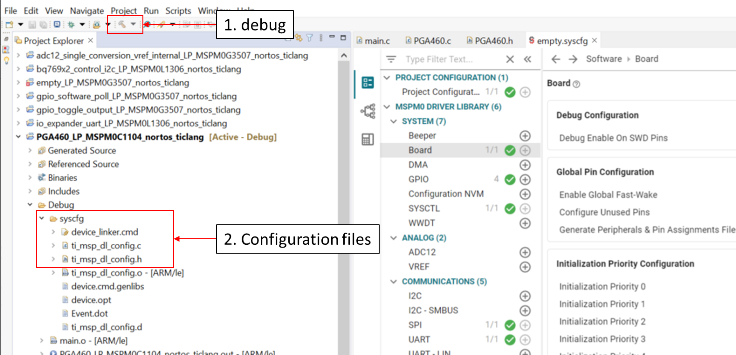
SysconfigAfter configuring the parameters of the peripherals, configuration files can be generated through debugging as shown in Figure 3-4.
 Figure 3-4 Configuration Files