SLAAEM1 June 2024 MSPM0C1104 , MSPM0C1104 , MSPM0L1105 , MSPM0L1105
3.5.1 Drive Method
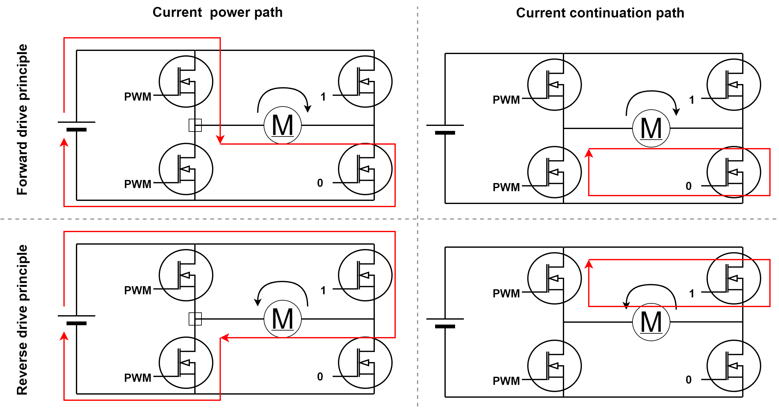
DC brushed motors have various drive methods. In this solution, a relatively simple drive method was used as shown in Figure 3-6. This method only requires a pair of complementary drive signals to operate a half-bridge. And one MOSFET in another half-bridge remains in a constant on-state, while the other is in a constant off-state, depending on the desired direction of rotation.
When the upper transistor in the left half-bridge is conducting, the power supply provides power to the motor, and the motor current flows from left to right. When the upper transistor is turned off, the motor continues to conduct through the lower transistors of the two half-bridges.
 Figure 3-6 Motor Drive Principles