SLAAEM1 June   2024 MSPM0C1104 , MSPM0C1104 , MSPM0L1105 , MSPM0L1105


  1.   1
  2.   Abstract
  3.   Trademarks
  4. 1Introduction
  5. 2System Architecture Introduction
  6. 3Hardware Design Introduction
    1. 3.1 Power Supply Circuit
    2. 3.2 Drive Circuit
    3. 3.3 Sampling Circuit
    4. 3.4 Main Controller Circuit
    5. 3.5 Control System Introduction
      1. 3.5.1 Drive Method
      2. 3.5.2 Control Method
  7. 4Software Design Introduction
    1. 4.1 Parameters Initialization
    2. 4.2 Direction Setup
    3. 4.3 Timer Interrupt
    4. 4.4 Closed Loop Controller
  8. 5Evaluation

Direction Setup

After initializing the parameters, it is necessary to configure the motor rotation according to the set parameters, which is realized through GPIO output high or low levels in main function, as shown in Figure 4-3. After that, enable interrupts, and commence calculating and updating the duty cycle.
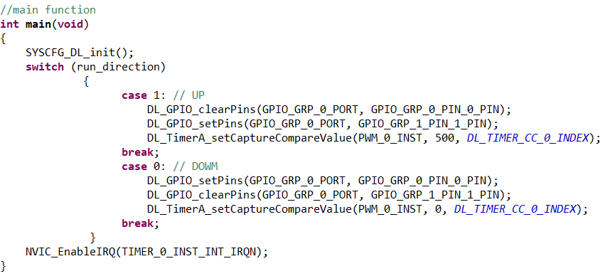
 Main Function Figure 4-3 Main Function