SLAAEM1 June 2024 MSPM0C1104 , MSPM0C1104 , MSPM0L1105 , MSPM0L1105
4.4 Closed Loop Controller
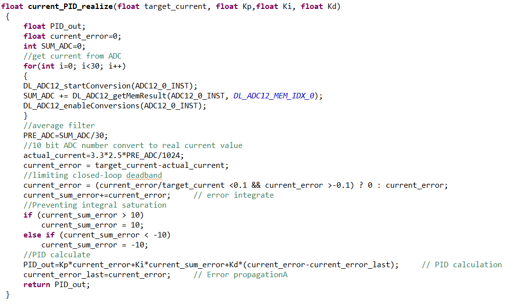
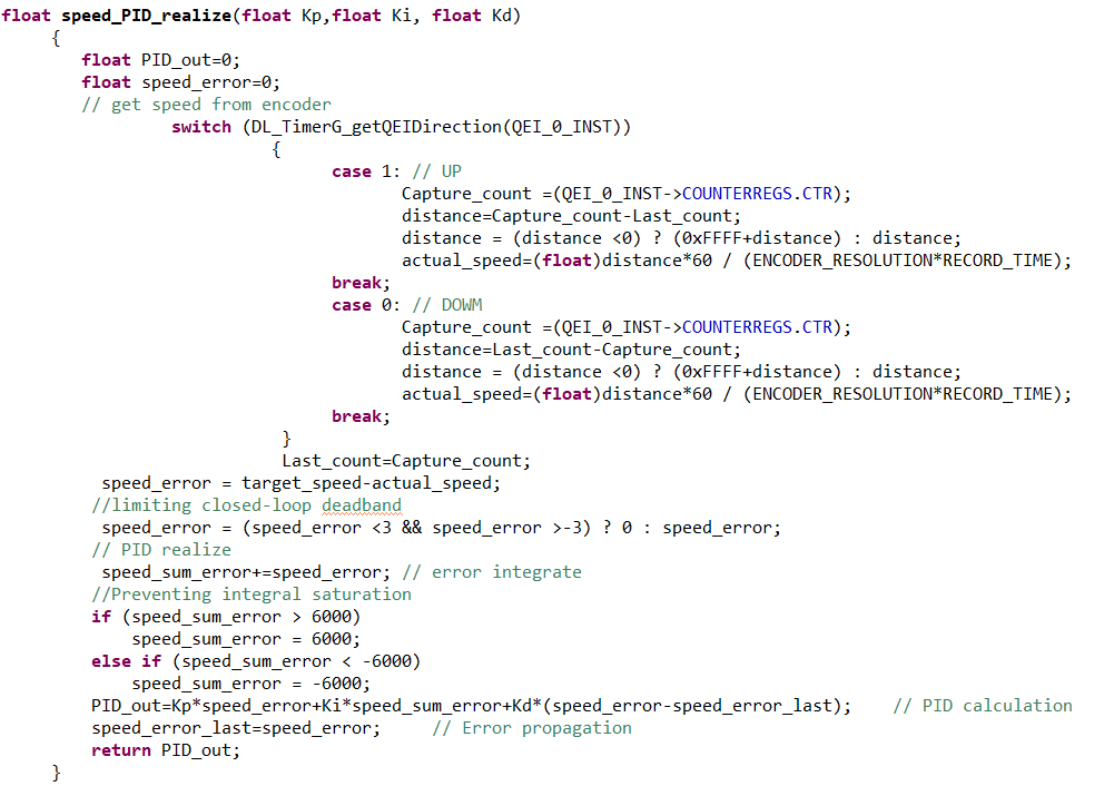
Current and speed closed loop controller are as shown in Figure 4-5 and Figure 4-6. In this solution, a positional PID algorithm is implemented. Consequently, in addition to constraining the output range, it is imperative to limit the integral value to avert integral saturation. Due to the limitations in ADC resolution, it is necessary to constrain the initial error value to prevent system oscillation caused by closed-loop dead zone. The sampling current of the ADC also needs to undergo averaging filtering to minimize the impact of noise on the sampling results and enhance the stability of the system.
The MSPM0C1104 features a configurable timer (TIMA) with built-in dead-time generation function, allowing for convenient generation of the required PWM waveform based on the PID calculation results.
 Figure 4-5 Current PID
 Figure 4-6 Speed PID