SLAAEO3 September 2024 MSPM0L2227 , MSPM0L2228
3.2 LCD Drive Basics
LCDs must drive with AC signals. A DC level on an LCD segment damages the LCD, typically less than 50mV DC voltage is allowed. The MSPM0 LCD module generates these types of AC waveforms automatically so that the user only has to specify if a segment is on or off – the internal hardware does the rest.
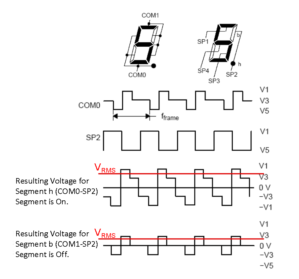
LCD segments have a charge applied to the crystals between two electrodes – a COMx line and an Sx segment line. The potential difference applied by these two electrodes is the waveform seen by the LCD segment.
The RMS voltage presented on an LCD segment determines whether the LCD segment is on or off. The example waveforms in Figure 3-2 show resulting waveforms (combination of COMx and Sx pin signals) of both an on and off segment. The on segment has a much larger RMS voltage applied on the on segment, rather than the off segment. Note that both segments have waveforms that have net zero DC voltage, but the RMS voltage of the on segment is higher, which causes the segment to turn on and look dark.
 Figure 3-2 Example LCD AC Waveforms