SLAAEO6 September 2024 MSPM0G3507
8 Results
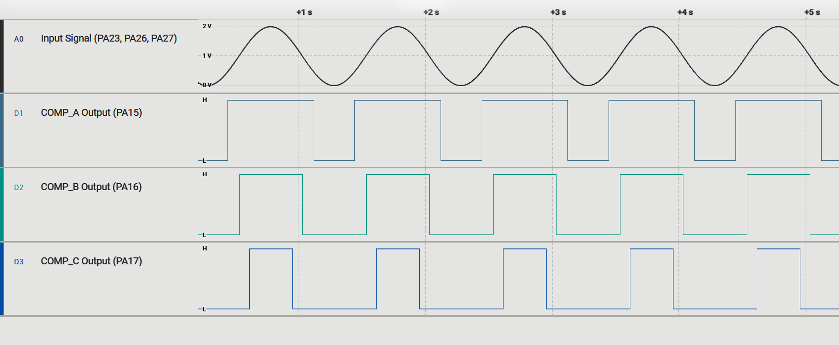
Figure 8-1 shows the results of the scanning comparator subsystem example. Emulated comparators A, B, and C had reference voltages set to 0.5V, 1.0V, and 1.5V, respectively. The same input signal was measured on each of the three emulated comparators.

Figure 8-1 Results
The scope reading demonstrates that
one physical comparator was able to mimic three comparators running at the same
time. This example code can be edited to fit different comparator numbers and
configurations by changing the functions within comp_hal.c.