SLAAEO6 September 2024 MSPM0G3507
1 Description
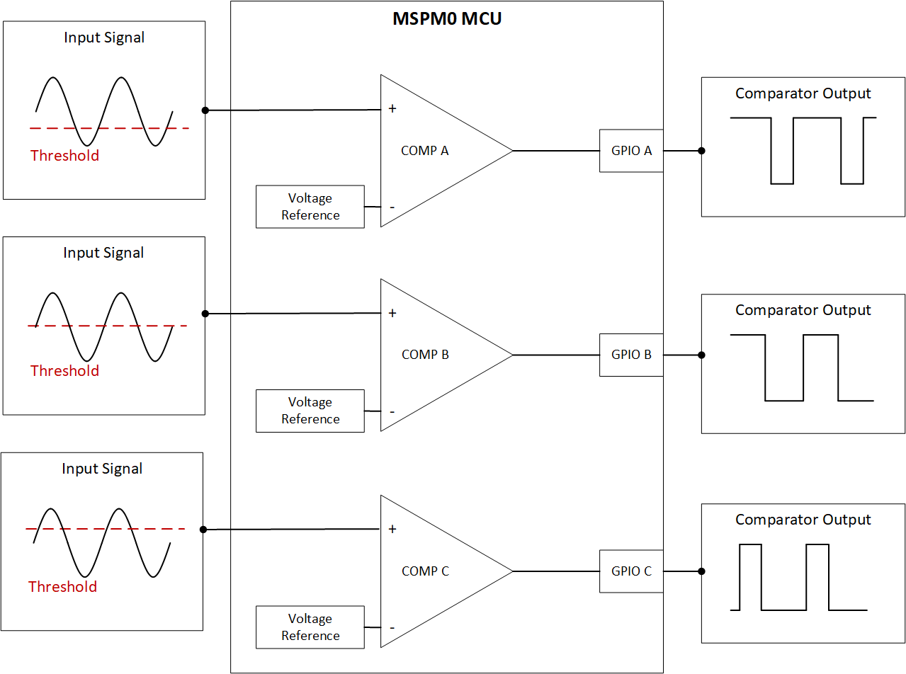
This subsystem demonstrates how to represent multiple comparators with a single integrated comparator and software in an MSPM0 microcontroller. The process allows the designer to maximize the comparator function and utilize more theoretical comparators than are physically on the device. This example specifically cycles through three different comparator configurations and input pins while setting three output pins with the results as shown in Figure 1-1.
 Figure 1-1 Theoretical Function of
Scanning Comparator Subsystem
Figure 1-1 Theoretical Function of
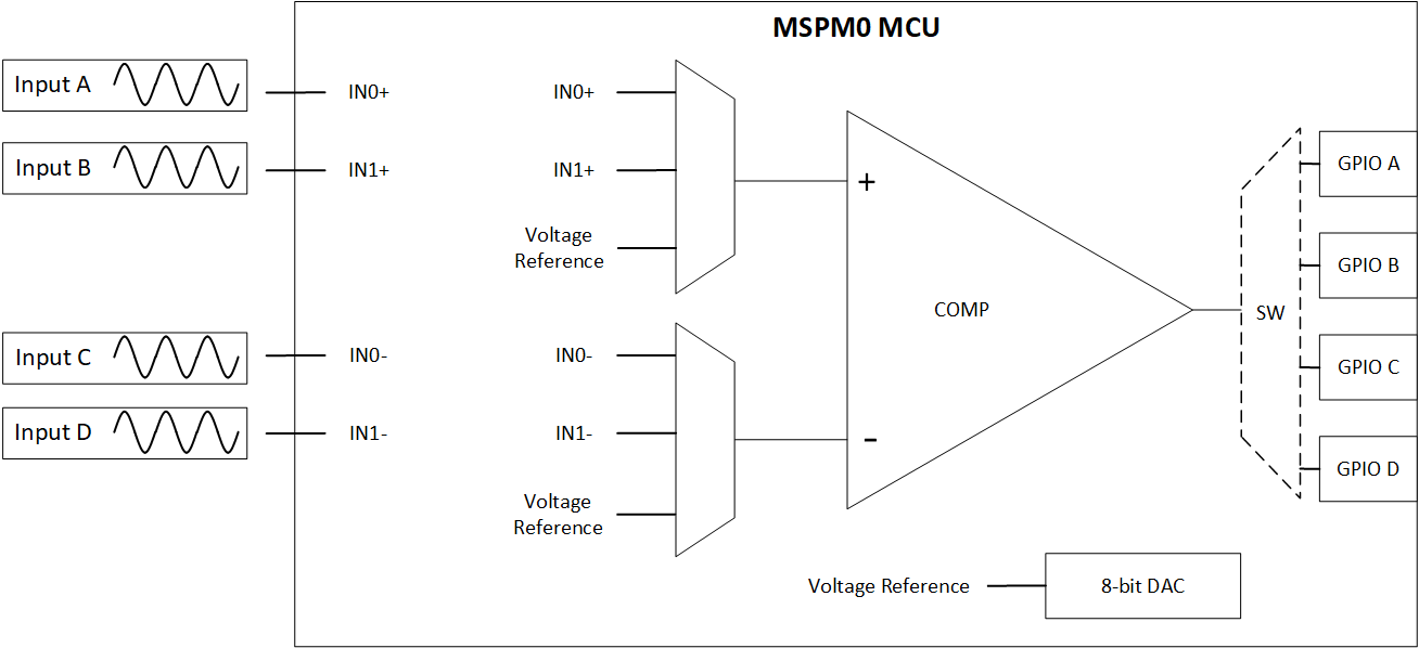
Scanning Comparator SubsystemUtilizing the customizable IO MUXing for the MSPM0 comparator, this example enables multiple signal inputs for the same comparator. The three signal inputs for this example are on the COMP_IN0+, COMP_IN0-, and COMP_IN1- pins as shown in Figure 1-2.
 Figure 1-2 Comparator Input and Output
MUXes