SLAAEP4 December 2024 BQ79616 , MSPM0G3507
2.1 LP-MSPM0G3507 Hardware Connection
For detailed information and schematics of LP-MSPM0G3507, see the MSPM0G3507 LaunchPad Development Kit User's Guide. LaunchPad™ pin configuration and pin connection with BQ79616 EVM, TCAN1046V-EVM are shown in Table 2-1.
Table 2-1 EVM Hardware Connection and
Function
| LaunchPad Pin Allocation | Target Device | |
|---|---|---|
| PB0 | Fault detection/GPIO | BQ79616 EVM J17-3 |
| PA10 | TX/UART | BQ79616 EVM J17-8 |
| PA11 | RX/UART | BQ79616 EVM J17-7 |
| PA12 | TX/CAN | TCAN1046EVM J5-6 |
| PA13 | RX/CAN | TCAN1046EVM J5-8 |
| PB21 | Enable CAN/GPIO | S2 on LaunchPad |
| GND | Power supply | BQ79616 EVM J17-5 |
| 3.3V | Power supply | BQ79616 EVM J17-6 |
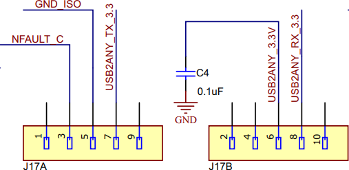
BQ79616 EVM J17 jumper is shown in Figure 2-2.
 Figure 2-2 BQ79616 EVM J17
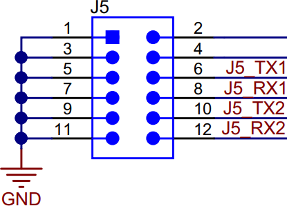
TCAN1046V-EVM J5 jumper allocation is shown in Figure 2-3, VIO and VCC are powered by LP-MSPM0G3507, to make communication properly, TCAN1046V-EVM and LP-MSPM0G3507 also share the same GND.
 Figure 2-3 TCAN1046 EVM J5