SLAAEP4 December 2024 BQ79616 , MSPM0G3507
2.2 BQ79616EVM Hardware Connection
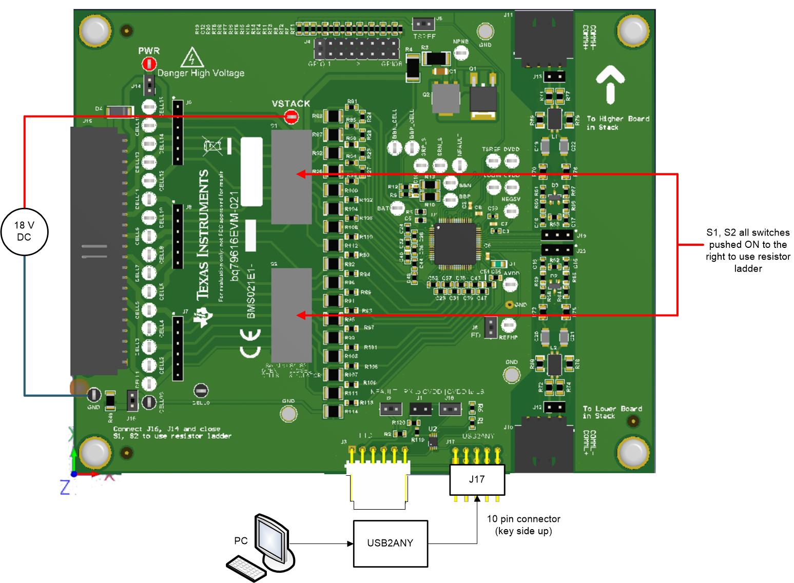
For the hardware connection of BQ79616EVM-021, see the BQ796xx-Q1 Evaluation Modules User's Guide, in this EVM, and note that the resistor's ladder is used to simulate the voltage of single cell. To power up the EVM, DC voltage source needs to be connected to VSTACK and GND, at the same time, S1 and S2 need to be turned to right, shown in Figure 2-4. This demo can support BQ79616EVM stack using daisy chain. More information for the hardware connection can be found in the Stacking BQ79616EVMs section of the BQ79616-Q1, BQ75614-Q1, BQ79656-Q1 Evaluation Modules User's Guide. BQ79616 hardware design can refer to BQ7961x-Q1 Design Recommendations for High Voltage Automotive BMS. The online version is also available.
 Figure 2-4 BQ79616EVM Setup Using DC Voltage With
Resistor Ladder