SLAAEP4 December 2024 BQ79616 , MSPM0G3507
4.1 Test Setup
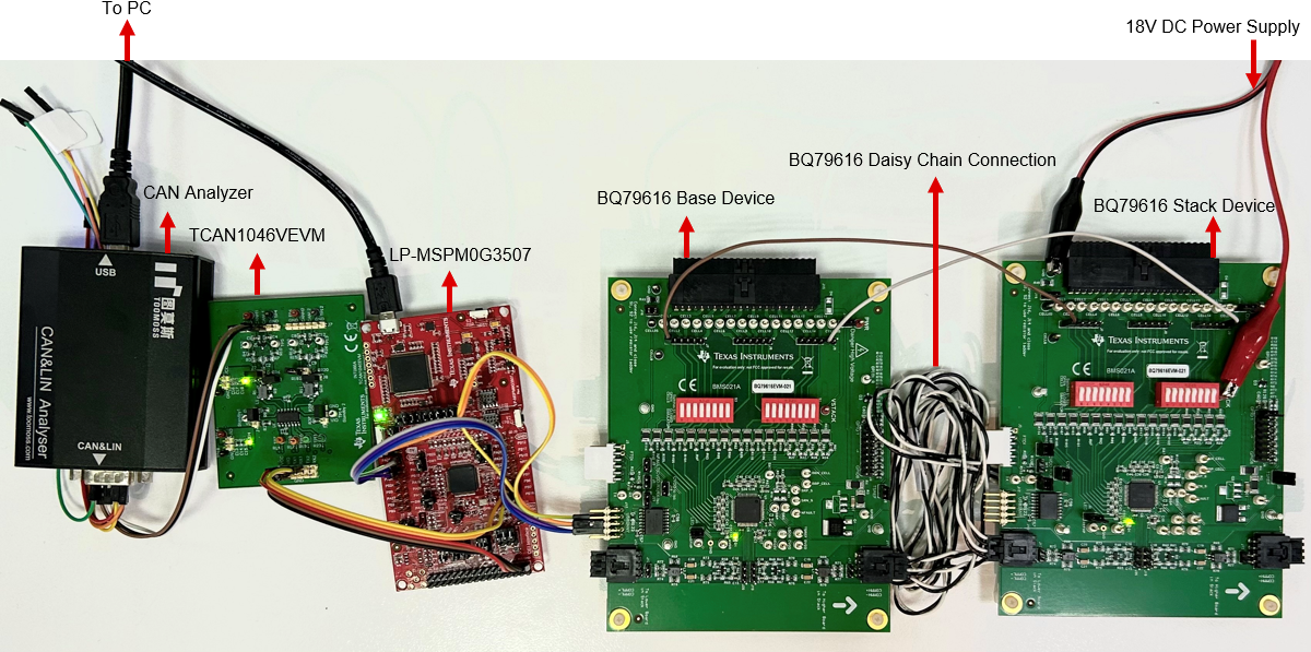
Here are the steps to set up the test environment. For the system diagram block, see Figure 2-1. Figure 4-1 is the actual test environment photo.
- Based on Figure 4-1, Figure 2-1, connect LP-MSPM0G3507 with two BQ79616 EVMs, TCAN1046VEVM and CAN analyzer. Both BQ79616 EVMs need to be powered, here we use a 18V DC power supply.
- Connect LP-MSPM0G3507 to PC using USB cable for debug purpose, and connect CAN Analyzer to PC to receive the CAN data.
- Import the BQ79616 demo code to CCS from the latest MSPM0-SDK, compile and start debugging on LP-MSPM0G3507.
- Open CAN Analyzer data receive window and CCS debug console window.
- Press S2 button (PB21) on LP-MSPM0G3507, to set the gTXMsg flag to true, and MSPM0 starts to send battery voltage data through debug printf port and CAN interface. The debug printf port send the data through XDS110 to CCS debug console window.
 Figure 4-1 Hardware Setup
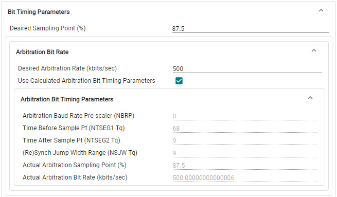
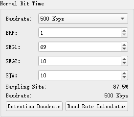
For the CAN bit timing settings, this demo code uses standard CAN, running at 500kbps and sampling point is 87.5%. Figure 4-2 is the MSPM0 CAN bit timing setting in System Configuration Tool. And in some CAN Analyzer host PC software, four CAN bit timing parameters (NBRP, NTSEG1 Tq, NTSEG2 Tq, NSJW Tq) need to be increased by 1 based on MSPM0 CAN bit timing settings to work properly, as shown in Figure 4-3.
 Figure 4-2 MSPM0 CAN Bit Timing
Parameters Settings
 Figure 4-3 CAN Analyzer CAN Bit Timing
Parameters Settings