SLAAEQ2 September 2024 MSPM0G1506 , MSPM0G3507
- 1
- Abstract
- Trademarks
- 1Introduction
-
2Example Mitigation Control Board Design
- 2.1 Overview of Mitigation Board Functions
- 2.2 Audible and Visible Detection Alarm
- 2.3 Freeze Detection (Water-Based Systems)
- 2.4 Isolation and or Safety Shut-off Valves (SSOVs) in the Refrigeration System to Limit Releasable Charge
- 2.5 Electronic Controls With A2L Logic to Perform Required Actions in The Event of a Leak — Such as Shutting off the Compressor and or Other Components
- 2.6 Ventilation and or Circulation Fans Within Cases or Walk-in Units
- 3Summary
- 4References
2 Example Mitigation Control Board Design
Figure 2-1 shows an example implementation of a mitigation board for HVAC systems. The board interfaces to the sensor module and based on the detection of refrigerant, or lack thereof, the board can carry out mitigation actions as necessary. More information on the sensor module design considerations can be found in A2L Refrigerant Adoption: Considerations and Requirements.
In some cases, the control signals from the mitigation control board are sent to the existing furnace control board to switch relays on or off for the compressor and the indoor blower fan. This can simplify the mitigation board design greatly and allow the preexisting furnace control board to execute the mitigation tasks.
This example design encompasses all of the mitigation tasks outlined in the ensuing section of this article to show a complete design that can be used for reference by the designer. The device selection is mainly driven by the lowest cost options available, allowing for a cost sensitive design that does not compromise the performance of executing the mitigation tasks.
 Figure 2-1 A2L Mitigation Control Board Block Diagram
Device Selection
MCU: For the MCU, there is not a need for high performance so the lowest cost MSPM0 was chosen (Figure 2-2). This option provides the necessary peripherals for communicating with the sensor module and other fieldbus devices and also provides PWM and GPIO functionality for relays, the peizo driver, and the indication LEDs.
 Figure 2-2 MSPM0C110 Functional Block Diagram
Relay Control: The relay control for the indoor blower fan and the compressor cutoff is comprised of several devices along with some discrete components as well.
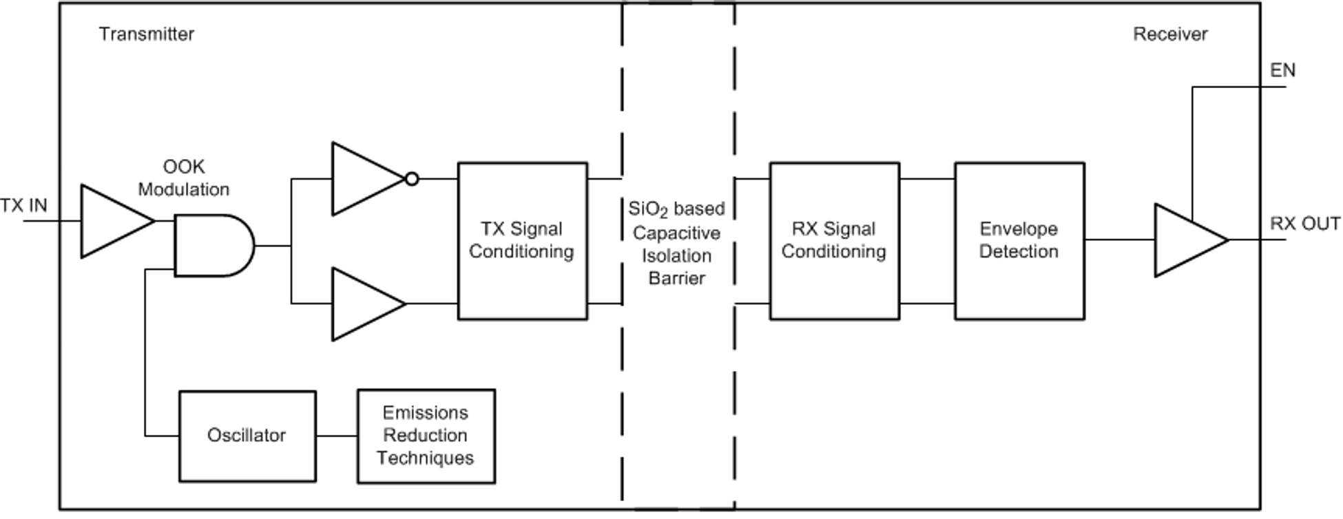
- Figure 2-3 is used as an isolation barrier between the MCU and the field side relay
control signal. This device is a 4-channel digital isolator which provides a
low-cost design with robust protection features.
 Figure 2-3 ISO7740 Functional
Block Diagram
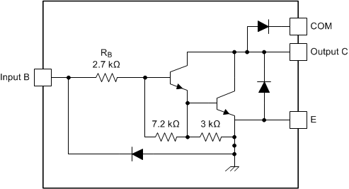
 - Figure 2-4 consists of seven NPN Darlington pairs that feature high-voltage outputs with
common-cathode clamp diodes for switching inductive loads. The collector-current
rating of a single Darlington pair is 500mA. The Darlington pairs can be
paralleled for higher current capability
 Figure 2-4 ULN2003A Darlington
Array Circuit
 - The TLV76050 is used as the LDO for the
isolated power rail to provide a 5V output for the field side. This device is
very low cost and provides enough current to drive multiple relay channels from
the field side of the ISO7740. A PWM from the MCU is used to generate the
isolated power rail as shown in Figure 2-5. The output of the secondary side is used by the Darlington array, and the
LDO output is used for the field side of the digital isolator. More information
on the SSR circuitry can be found in the 24-VAC Multi-Channel Solid-State
Relay Reference Design Using Digital Isolator.
 Figure 2-5 Open Loop Flyback for
Isolated Relay Control
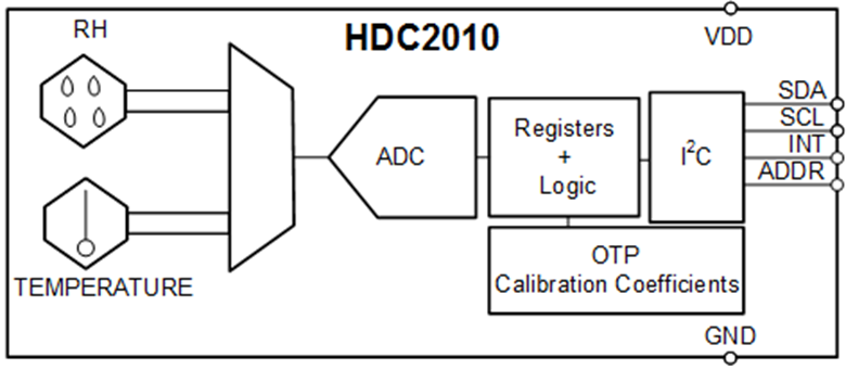
Freeze Detection: For water based systems needing freeze detection, a temperature and humidity sensor can be used to indicate this event. This design leverages the HDC2010 which is a low-cost digital temperature and humidity sensor that can be mounted on the mitigation board, or even off-board near the heat exchanger depending on the use case as shown in Figure 2-6. The HDC2010 is a humidity and temperature sensor that provides high accuracy measurements with very low power consumption. The sensor is factory-calibrated to 0.2°C temperature accuracy and 2% relative humidity accuracy and includes a heating element to burn away condensation and moisture for increased reliability.
 Figure 2-6 HDC2010 Functional Block Diagram
Audio Driver: For the audio alarm, the DRV8220 is selected as a low cost piezo driver. Although this device is marketed as a half-bridge motor drive, the device can also be leveraged as a piezo speaker driver for the audio alarm. The DRV8220 supports multiple control interface modes including PWM (IN1/IN2), phase/enable (PH/ EN), independent half-bridge, and parallel half-bridge. Each interface supports a low-power sleep mode to achieve ultra-low quiescent current draw by shutting down most of the internal circuitry. The device can supply up to 1.76A of output current and operates with a supply voltage from 4.5 to 18V as shown in Figure 2-7.
 Figure 2-7 DRV8220 Piezo Speaker Driver Block Diagram
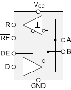
Fieldbus Interface: For the fieldbus communication, there are a variety of communication interfaces that can be chosen based on the target communication protocol. Many sensor modules on the market today use RS-485 as the primary communication protocol between the sensor module and the mitigation control board. For this reason, the THVD1500 is chosen as the communication interface for the example mitigation control board as shown in Figure 2-8. The THVD1500 is a low-cost, low-power half-duplex RS-485 transceiver designed for data transmission up to 500kbps.
 Figure 2-8 THVD1500 Functional Block Diagram