SLASEJ4C April 2017 – February 2023 PGA460
PRODUCTION DATA
- 1 Features
- 2 Applications
- 3 Description
- 4 Revision History
- 5 Pin Configuration and Functions
-
6 Specifications
- 6.1 Absolute Maximum Ratings
- 6.2 ESD Ratings
- 6.3 Recommended Operating Conditions
- 6.4 Thermal Information
- 6.5 Internal Supply Regulators Characteristics
- 6.6 Transducer Driver Characteristics
- 6.7 Transducer Receiver Characteristics
- 6.8 Analog to Digital Converter Characteristics
- 6.9 Digital Signal Processing Characteristics
- 6.10 Temperature Sensor Characteristics
- 6.11 High-Voltage I/O Characteristics
- 6.12 Digital I/O Characteristics
- 6.13 EEPROM Characteristics
- 6.14 Timing Requirements
- 6.15 Switching Characteristics
- 6.16 Typical Characteristics
-
7 Detailed Description
- 7.1 Overview
- 7.2 Functional Block Diagram
- 7.3
Feature Description
- 7.3.1 Power-Supply Block
- 7.3.2 Burst Generation
- 7.3.3 Analog Front-End
- 7.3.4 Digital Signal Processing
- 7.3.5 System Diagnostics
- 7.3.6
Interface Description
- 7.3.6.1 Time-Command Interface
- 7.3.6.2
USART Interface
- 7.3.6.2.1 USART Asynchronous Mode
- 7.3.6.2.2 One-Wire UART Interface
- 7.3.6.2.3 Ultrasonic Object Detection Through UART Operations
- 7.3.6.3 In-System IO-Pin Interface Selection
- 7.3.7 Echo Data Dump
- 7.3.8 Low-Power Mode
- 7.3.9 Transducer Time and Temperature Decoupling
- 7.3.10 Memory CRC Calculation
- 7.3.11 Temperature Sensor and Temperature Data-Path
- 7.3.12 TEST Pin Functionality
- 7.4 Device Functional Modes
- 7.5 Programming
- 7.6 Register Maps
- 8 Application and Implementation
- 9 Device and Documentation Support
- 10Mechanical, Packaging, and Orderable Information
7.3.6.2.1.7 Diagnostic Field
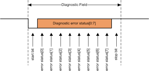
As described in the GUID-048C59B8-7835-47F1-BC5D-944AF6850CC6.html#TITLE-SLASEC8X3845 section, the PGA460 device begins the response transmission with a diagnostic data field. This field contains UART communication error bits. If a particular bit is set to 1 then the associated communication error has occurred sometime between the last response operation and the current response operation. After a response operation is performed, the communication error bits are cleared. The diagnostic field is included in the peripheral generated checksum calculation. #X6748 shows the diagnostic data field.
 Figure 7-27 UART Diagnostic Data Field
Table 7-4 lists the diagnostic data error status bits.
The error status[7:6] bits in the diagnostic field are set to 01b so that the bit time transmitted by the peripheral can be easily measured. If more error status is required, these bit locations can be used to transmit the additional error status.
| BIT | UART_DIAG = 0 | UART_DIAG = 1 |
|---|---|---|
| Error status [0] | PGA460 Device Busy | |
| Error status [1] | Sync field bit rate too high (>115200 bps) | Threshold settings CRC error |
| Sync field bit rate too low (>115200 bps) | ||
| Error status [2] | Consecutive sync field bit widths do not match | Frequency diagnostics error |
| Error status [3] | Invalid checksum received from controller (essentially a calculated peripheral checksum does not match the checksum transmitted by the controller) | Voltage diagnostics error |
| Error status [4] | Invalid command sent from controller | Logic 0 |
| Error status [5] | General communication error:
| EEPROM CRC error or TRM CRC error |
| Error status [6] | Logic 1 | |
| Error status [7] | Logic 0 | |