SLAU320AJ July 2010 – May 2021
- Trademarks
- 1Introduction
-
2Programming Using the JTAG Interface
- 2.1 Introduction
- 2.2
Interface and Instructions
- 2.2.1 JTAG Interface Signals
- 2.2.2 JTAG Access Macros
- 2.2.3 Spy-Bi-Wire (SBW) Timing and Control
- 2.2.4 JTAG Communication Instructions
- 2.3
Memory Programming Control Sequences
- 2.3.1 Start-Up
- 2.3.2 General Device (CPU) Control Functions
- 2.3.3 Accessing Non-Flash Memory Locations With JTAG
- 2.3.4 Programming the Flash Memory (Using the Onboard Flash Controller)
- 2.3.5 Erasing the Flash Memory (Using the Onboard Flash Controller)
- 2.3.6 Reading From Flash Memory
- 2.3.7 Verifying the Target Memory
- 2.3.8 FRAM Memory Technology
- 2.4
JTAG Access Protection
- 2.4.1 Burning the JTAG Fuse - Function Reference for 1xx, 2xx, 4xx Families
- 2.4.2 Programming the JTAG Lock Key - Function Reference for 5xx, 6xx, and FRxx Families
- 2.4.3 Testing for a Successfully Protected Device
- 2.4.4 Unlocking an FRAM Device in Protected and Secured Modes
- 2.4.5 Memory Protection Unit Handling
- 2.4.6 Intellectual Property Encapsulation (IPE)
- 2.4.7 FRAM Write Protection
- 2.5 JTAG Function Prototypes
- 2.6 JTAG Features Across Device Families
- 2.7 References
- 3JTAG Programming Hardware and Software Implementation
- 4Errata and Revision Information
- 5Revision History
2.2.3.5.1 SetTCLK and ClrTCLK
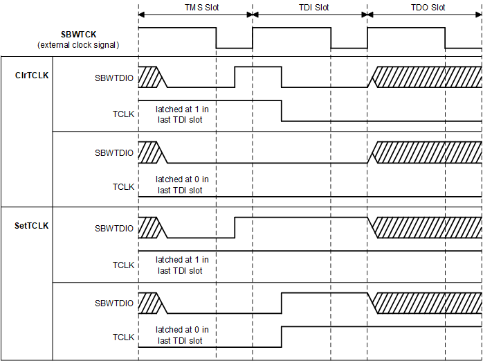
If the JTAG TAP controller is in the Run-Test/Idle state, the TDI slot can provide the TCLK signal (that is, it can clock the target CPU). Following this implementation, the generation of a complete TCLK clock cycle requires two TDI slots, one of which sets the TCLK signal and one of which clears it. In each case, the SBWTDIO signal must be set low in the TMS slot to keep the TAP controller from leaving the Run-Test/Idle state. To provide only a falling edge for ClrTCLK, the SBWTDIO signal must be set high before entering the TDI slot. The corresponding rising edge must occur in the low phase of SBWTCK in the TMS slot. Otherwise it would be interpreted as a trigger for TMS = 1 and the TAP controller would leave Run-Test/Idle mode.
Figure 2-11 shows handling of TCLK in SBW mode. See the reference functions SetTCLK_sbw and ClrTCLK_sbw in the MSP430 Replicator project (slau320.zip) for software implementation. The provided code example for the MSP430Xv2 architecture uses preprocessor definitions to enable a better layered software architecture. The upper software layers can simply reference the SetTCLK and ClrTCLK symbols while the actual implementation symbols are SetTCLK_4wire and ClrTCLK_4wire for 4-wire JTAG and SetTCLK_sbw and ClrTCLK_sbw for Spy-Bi-Wire (SBW).
 Figure 2-11 Synchronization of TDI and TCLK During Run-Test/Idle