SLAU857A May 2021 – July 2021 MSP430FR2476 , MSP430FR2512 , MSP430FR2522 , MSP430FR2532 , MSP430FR2533 , MSP430FR2632 , MSP430FR2633 , MSP430FR2672 , MSP430FR2673 , MSP430FR2675 , MSP430FR2676
3.1.1 Button or Proximity Sensor
Both buttons and proximity sensors are zero-dimensional sensors. The principle of both implementations is the same. The difference is that proximity sensing tends to have higher sensitivity and a larger sensor enclosing area.
Self-capacitive button:
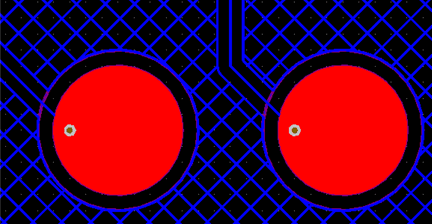
As Figure 3-1 shows, the self-inductive button is mainly composed of copper clad connected to the CAP I/O pins and an insulating covering material. The button is also surrounded by a grounded copper clad separated from the button pad by a ring gap. Each button requires 1 MCU CAP I/O pin.
 Figure 3-1 Self-Capacitive Button PCB
Mutual-capacitive button:
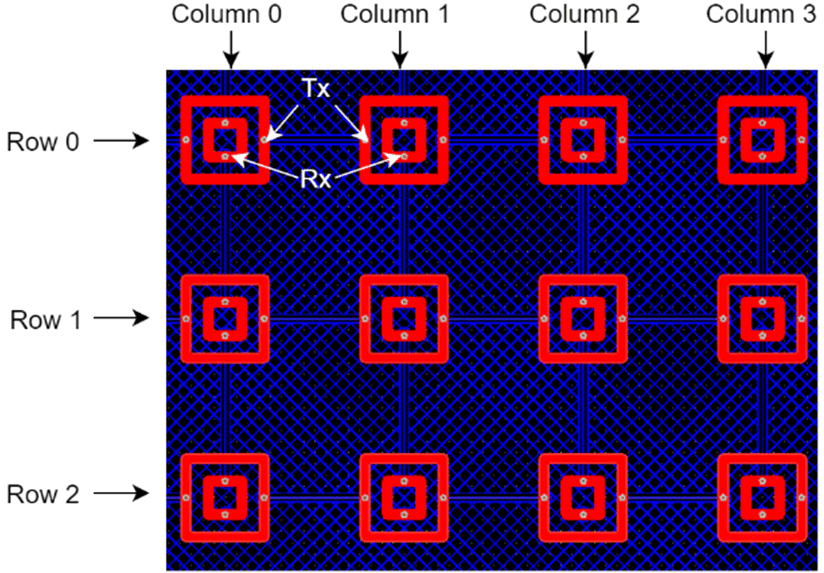
In applications that require a large number of buttons, capacitive sensors can be arranged in a matrix, and each button is connected to 2 CAP I/O pins, with 1 CAP I/O pin connected to each row or column of buttons. As shown in Figure 3-2, the two box-shaped copper clad inside and outside are Tx and Rx. The program supports multi-button touch. X rows by Y columns require X+Y MCU CAP I/O pins.
 Figure 3-2 Mutual-Capacitive Button Matrix PCB
Self-capacitive proximity sensor:
Typically, proximity sensors use the self-capacitive scheme. The main reasons are that self-capacitive detection has a longer detection distance than mutual-capacitive detection, more flexible wiring and structure, and a higher signal-to-noise ratio. The PCB outer circle in Figure 3-3 shows the proximity sensor. In addition to using PCB copper to form a proximity sensor, wires or even conductive metal structures can also be used. A self-inductive proximity sensor requires 1 MCU CAP I/O pin.
 Figure 3-3 Mutual-Induction Proximity-Sensing PCB