SLAU873D January 2023 – October 2024
- 1
- Abstract
- Trademarks
- 1Getting Started
-
2Hardware
- 2.1 Jumper Map
- 2.2 Block Diagram
- 2.3
Hardware Features
- 2.3.1 MSPM0G3507 MCU
- 2.3.2 XDS110-ET Onboard Debug Probe With EnergyTrace Technology
- 2.3.3 Debug Probe Connection Isolation Jumper Block
- 2.3.4 Application (or Backchannel) UART
- 2.3.5 Using an External Debug Probe Instead of the Onboard XDS110-ET
- 2.3.6 Using the XDS110-ET Debug Probe With a Different Target
- 2.3.7 Special Features
- 2.4 Power
- 2.5 External Power Supply and BoosterPack Plug-in Module
- 2.6 Measure Current Draw of the MSPM0 MCU
- 2.7 Clocking
- 2.8 BoosterPack Plug-in Module Pinout
- 3Software Examples
- 4Resources
- 5Schematics
- 6Revision History
2.3.7.3 Light Sensor
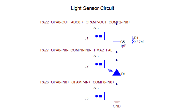
A light sensor circuit is provided on the board using the photodiode in the configuration shown in Figure 2-9. The jumper connections between this circuit and the MSPM0 are populated by default so the photodiode is in circuit. The jumpers can be removed to place the photodiode out of circuit so the MSPM0 connections can be used for other evaluation purposes.
 Figure 2-9 Light Sensor Circuit
This circuit is intended to be used with the internal OPA of the MSPM0 in an transimpedance configuration to drive the circuit. The OPA output is internally set to an ADC channel for sampling.