SLAU880C December 2022 – May 2024 ULC1001
- 1
- Abstract
- Trademarks
- 1General Texas Instruments High Voltage Evaluation (TI HV EVM) User Safety Guidelines
- 2Introduction
- 3Getting Started
- 4System Overview
- 5GUI Overview
- 6Hardware Design Files
- 7Revision History
5.5.1 Monitor Communication Status
The GUI status bar is located in the South
Pane shown in Figure 5-15. The status bar allows communication status to be monitored. The communication mode health
indicator at the bottom right is lit yellow when not connected, lit green when connected, or
unlit when in demo mode. When first opened, the GUI automatically attempts to connect with the
ULC1001-DRV290x EVM via the USB2ANY interface. Upon successful connection, the green lit
connected indicator appears as in the bottom right corner of the status bar. This
connection takes approximately 25 seconds. Communication issues can include a faulty USB2ANY
interface connection, an incorrect target address, or an incomplete GUI initialization. The
Read/Write Status Indicator on the bottom left of the status bar cycles quickly
through register names when the GUI is reading or writing registers from the ULC1001-DRV290x
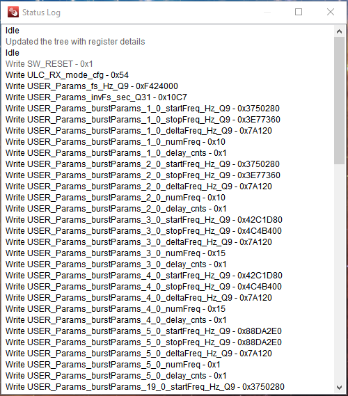
EVM. Double clicking the Read/Write Status Indicator on the status bar opens a floating
window which displays the entire status log, shown in Figure 5-16. Right-clicking this floating window shows the options to clear log or save the log or set
the size. The status log is meant for recording Register Read/Write sequences. To create
register read/write scripts, see Section 5.5.9.
 Figure 5-15 GUI Status Bar
 Figure 5-16 GUI Status Log
 Figure 5-15 GUI Status Bar
 Figure 5-16 GUI Status Log