SLAU889 December 2022
6 PCB Layout and 3D Diagram
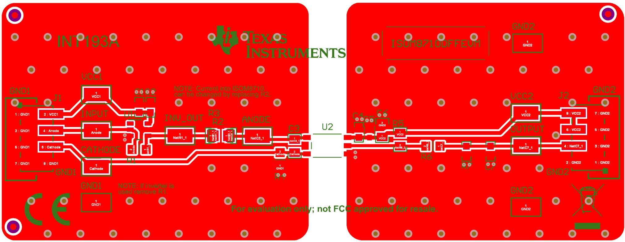
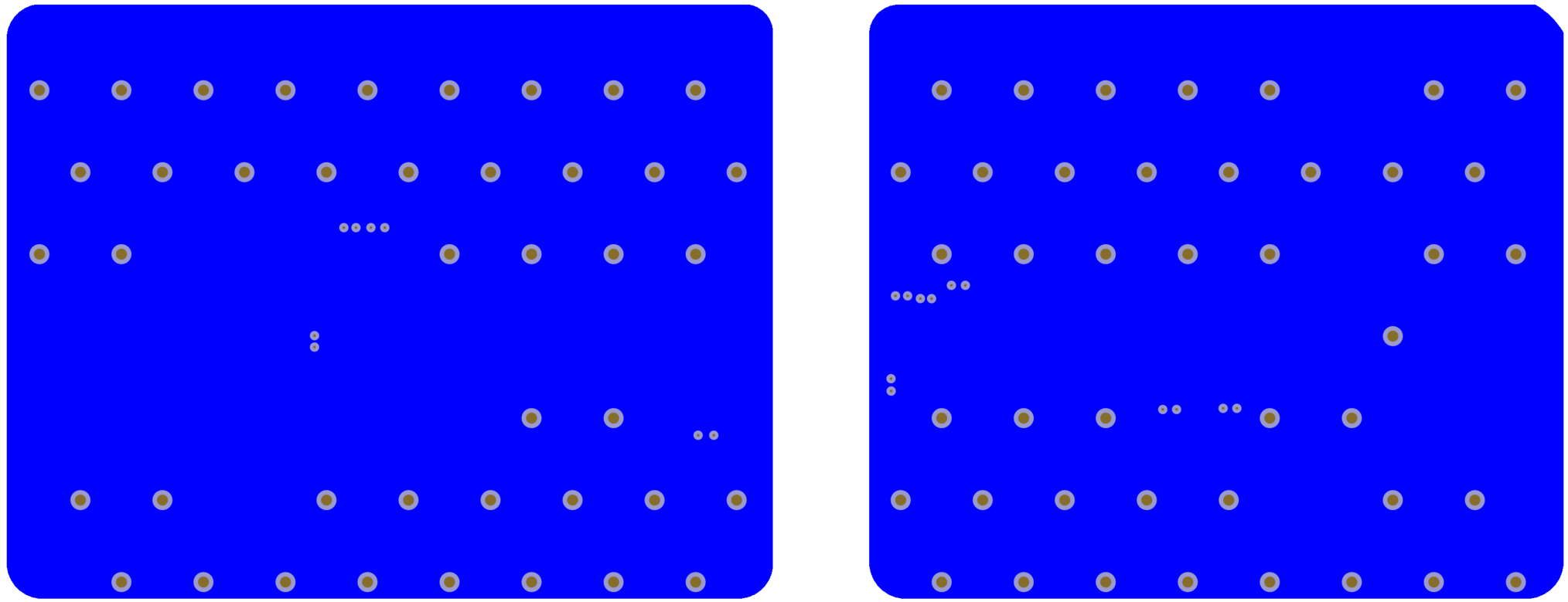
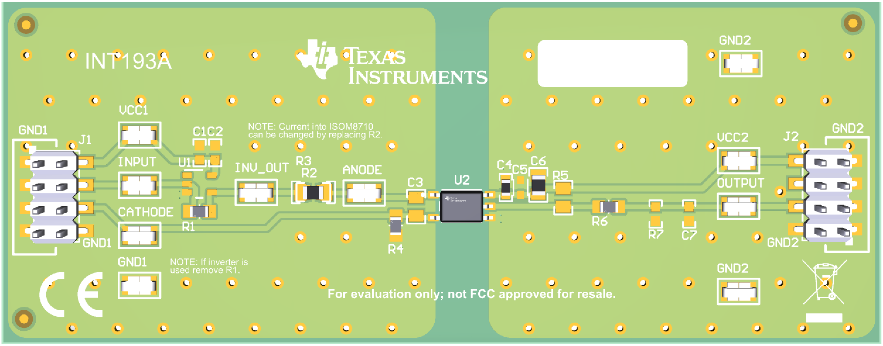
Figure 6-1 and Figure 6-2 show the printed-circuit board (PCB) layout top and bottom, respectively, and Figure 6-3 shows a 3D diagram of the EVM PCB.
 Figure 6-1 ISOM8710DFFEVM PCB Layout -
Top
 Figure 6-2 ISOM8710DFFEVM PCB Layout -
Bottom
 Figure 6-3 ISOM8710DFFEVM PCB 3D
Diagram