SLAU899 August   2023


  1.   1
  2.   Description
  3.   Features
  4.   4
  5. 1Evaluation Module Overview
    1. 1.1 Introduction
    2. 1.2 Kit Contents
    3. 1.3 Specification
    4. 1.4 Device Information
  6. 2Hardware
    1. 2.1 EVM Setup and Operation
    2. 2.2 Pin Configuration of the ISOM8110 Single-Channel Opto-Emulator with Analog Transistor Output
  7. 3Hardware Design Files
    1. 3.1 Schematics
    2. 3.2 PCB Layout and 3D Diagram
    3. 3.3 Bill of Materials
  8. 4Additional Information
    1.     Trademarks

PCB Layout and 3D Diagram

Figure 4-2 and Figure 4-3 show the printed-circuit board (PCB) layout top and bottom, respectively, and Figure 4-4 shows a 3D diagram of the EVM PCB.
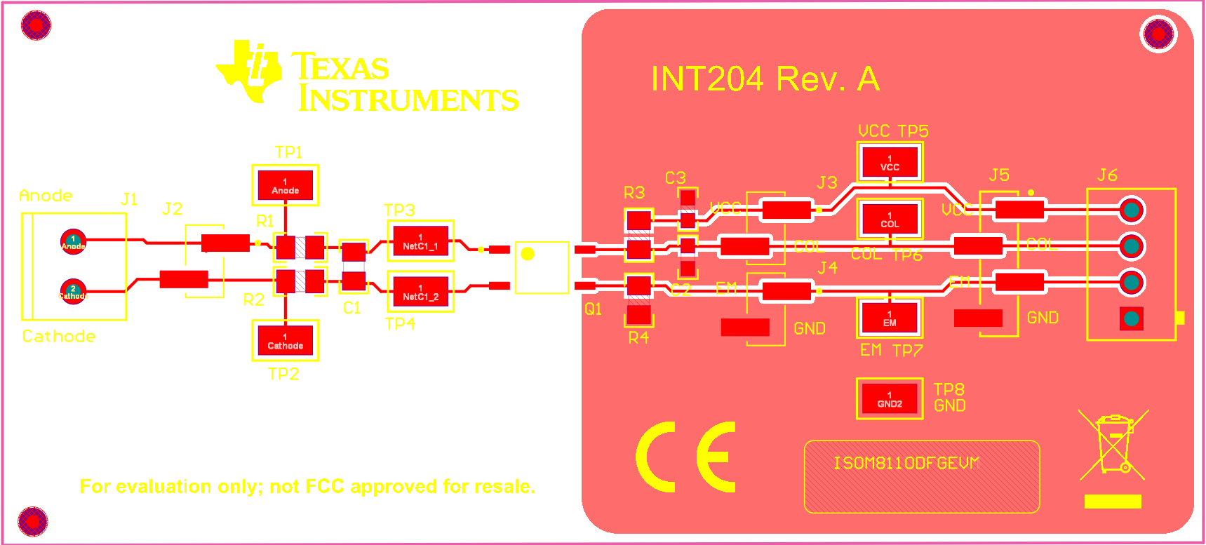
GUID-20230828-SS0I-Z5KW-GB3J-RDCSWCTFCTBP-low.png Figure 3-2 ISOM8110DFGEVM PCB Layout - Top
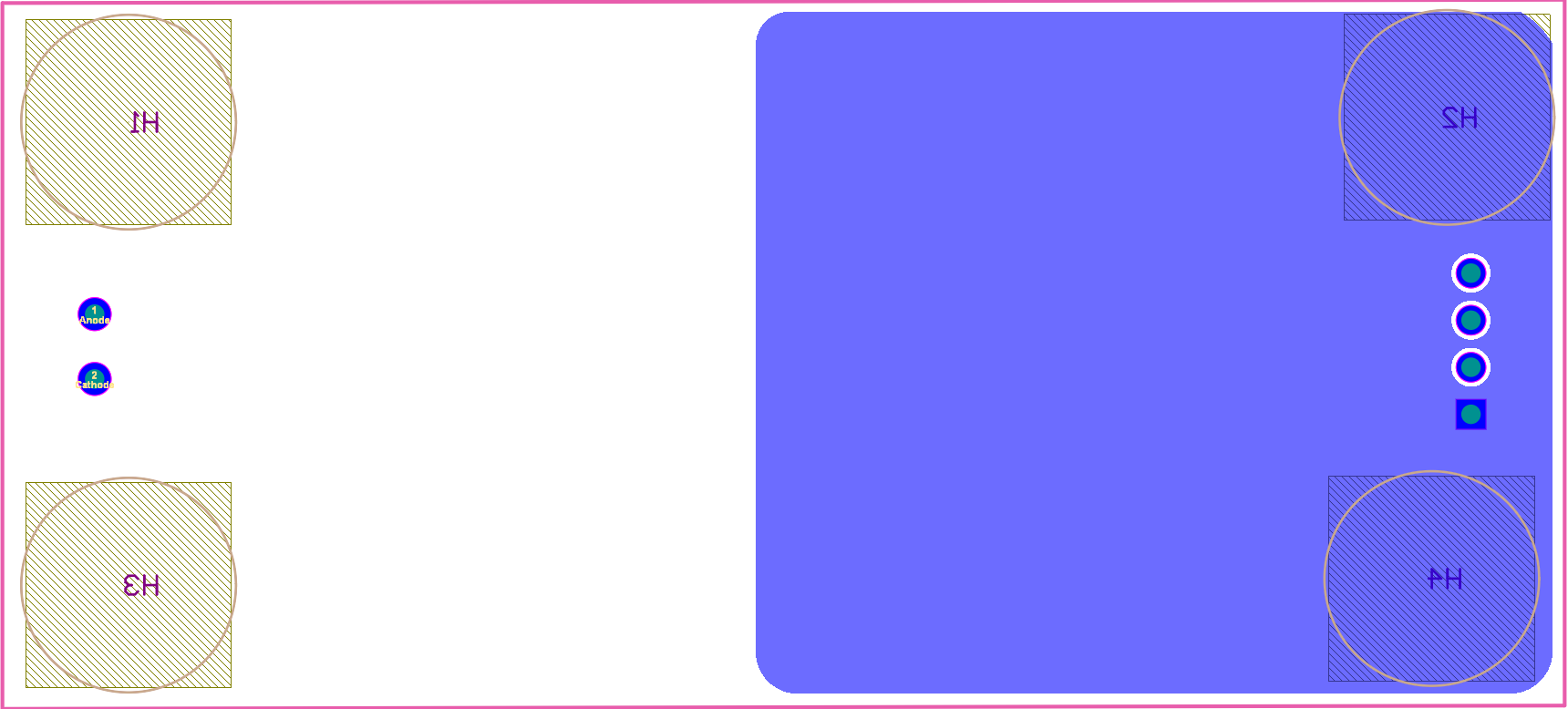
GUID-20230828-SS0I-SCBX-2RDW-78P9SGQBSTX4-low.png Figure 3-3 ISOM8110DFGEVM PCB Layout - Bottom
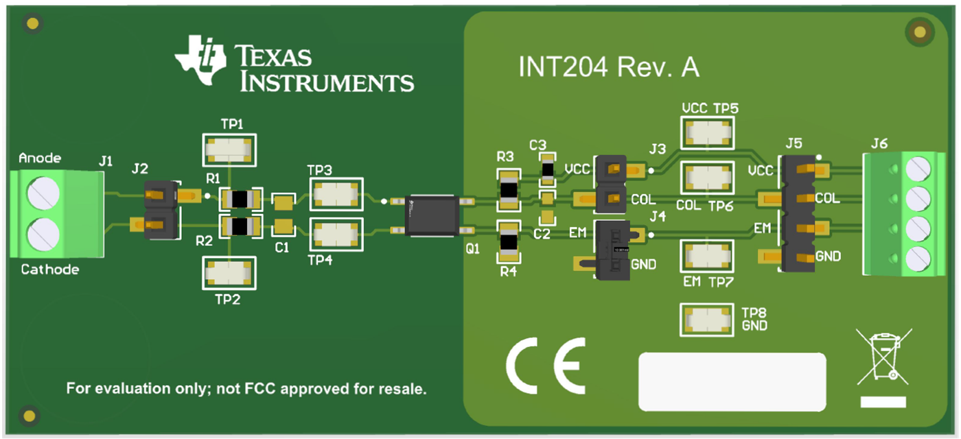
GUID-20230823-SS0I-QJQG-VCBC-RWJCWXDK7N2P-low.png Figure 3-4 ISOM8110DFGEVM PCB 3D Diagram