SLAU900 November 2023
3.2.1 Starting the Software
To launch the software, navigate to the SMART-DAC-EVM folder in the Start menu, and select the SMART-DAC-EVM icon.
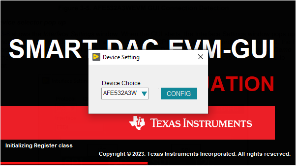
Figure 4-3 shows the Device Selector window that pops up on start up. This window contains a drop-down menu to select which device register map is loaded into the GUI. Select the AFE532A3W when using the AFE532A3WEVM.
 Figure 3-3 Device Selector
Figure 4-4 shows that if the onboard controller is connected correctly, the status bar at the bottom of the screen displays CONNECTED. If the controller is not properly connected or not connected at all, the status displays DEMO. If the GUI is not displaying the CONNECTED status while the EVM is connected, unplug and reconnect the EVM, and then relaunch the GUI software. If the display continues to display DEMO, uncheck the Demo Mode checkbox (see Figure 4-6, upper-right corner).
 Figure 3-4 GUI Connection
Detection
Figure 3-4 GUI Connection
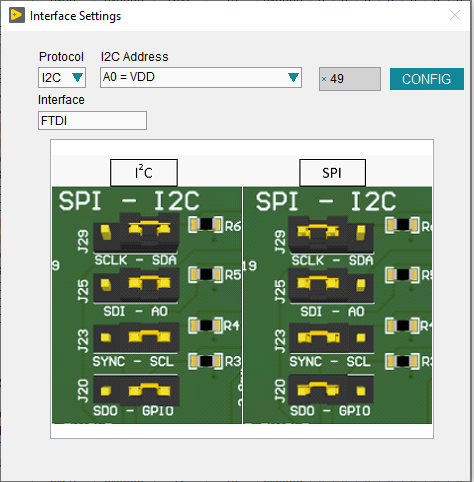
DetectionFigure 4-5 shows the Interface Settings window. When the GUI starts, the Interface Settings window pops up. This window contains drop-down menus that select protocol (SPI or I2C) and, if I2C protocol is selected, the I2C device address. The menu does not pop up if the GUI starts in Demo mode. In this case, uncheck the Demo Mode checkbox. If the interface must be updated again, toggle the Demo Mode checkbox for the menu to reappear.
 Figure 3-5 Interface Settings