SLAU903 October   2023


  1.   1
  2.   Description
  3.   Get Started
  4.   Features
  5.   Applications
  6.   6
  7. 1Evaluation Module Overview
    1. 1.1 Introduction
    2. 1.2 Kit Contents
    3. 1.3 Specification
    4. 1.4 Device Information
  8. 2Hardware
    1. 2.1 Hardware Overview
    2. 2.2 AC-MB Settings
      1. 2.2.1 Audio Serial Interface Settings
        1. 2.2.1.1 USB Mode
        2. 2.2.1.2 Optical or Auxiliary Analog Audio Input Mode
        3. 2.2.1.3 External Audio Interface Mode
      2. 2.2.2 AC-MB Power Supply
    3. 2.3 TAx5x1xQ1EVM-K Hardware Settings
      1. 2.3.1 TAx5412-Q1 EVM Input Hardware Settings
        1. 2.3.1.1 Line Inputs
        2. 2.3.1.2 On-board Microphone Input
      2. 2.3.2 TAC541x-Q1 EVM Output Hardware Settings
    4. 2.4 Diagnostics Hardware Setup
      1. 2.4.1 Short to MICBIAS Setup
      2. 2.4.2 Short to VBAT Setup
      3. 2.4.3 Shorted Input Pins Setup
      4. 2.4.4 Short to GND Setup
    5. 2.5 GPIO1 Hardware Configurations
  9. 3Software
    1. 3.1 Software Description
    2. 3.2 PurePath Console 3 Installation
      1. 3.2.1 USB Audio Setup
    3. 3.3 TAx5x1x-Q1 EVM GUI
      1. 3.3.1 Software Overview
      2. 3.3.2 Configuration View
        1. 3.3.2.1 Device Config Tab
        2. 3.3.2.2 Record Config Tab
        3. 3.3.2.3 Playback Config Tab
        4. 3.3.2.4 Audio Serial Bus Tab
          1. 3.3.2.4.1 Configuring Primary Audio Serial Bus
          2. 3.3.2.4.2 Configuring Secondary Audio Serial Bus
          3. 3.3.2.4.3 Example Configuring I2S Interface
        5. 3.3.2.5 GPIO/Interrupts Tab
        6. 3.3.2.6 Advanced Tabs
          1. 3.3.2.6.1 Diagnostic Tab
          2. 3.3.2.6.2 Programmable Biquads Tab
          3. 3.3.2.6.3 Automatic Gain Control (AGC) Tab
          4. 3.3.2.6.4 Voice/Ultrasonic Auto Detection (VAD/UAD) Tab
          5. 3.3.2.6.5 Mixer Tab
          6. 3.3.2.6.6 Tone Generation Tab
          7. 3.3.2.6.7 Limiter Tab
        7. 3.3.2.7 End System Integration View
        8. 3.3.2.8 Register Map View
        9. 3.3.2.9 I2C Monitor View
    4. 3.4 Configuration Examples
    5. 3.5 System Overview
  10. 4Hardware Design Files
    1. 4.1 Schematics
    2. 4.2 PCB Layouts
    3. 4.3 Bill of Materials (BOM)
      1. 4.3.1 TAC5412-Q1 EVM Bill of Materials
      2. 4.3.2 TAC5311-Q1 EVM Bill of Materials
      3. 4.3.3 TAA5412-Q1 EVM Bill of Materials
  11. 5Additional Information
    1. 5.1 Trademarks
  12. 6References

TAx5x1x-Q1 EVM GUI

Open the PPC3 application in the directory chosen for the GUI installation in Section 3.2. Figure 3-3 shows the resulting app center window. Click on the TAC5x1x-Q1 app tile.
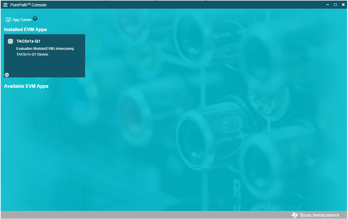
GUID-20230627-SS0I-PG6N-SM5T-SV0X3S1S5RL3-low.pngFigure 3-3 PurePath Console 3 App Center

The TAC5x1x-Q1 GUI is designed to work with up to four devices at any time. Select the device( for example, TAA5412-Q1 as shown in the Figure 3-4). There can be other device variants in the pull-down menu. The subsequent PPC3 Software sections below are based on this device example. Choose the 1 device radio button and click New.
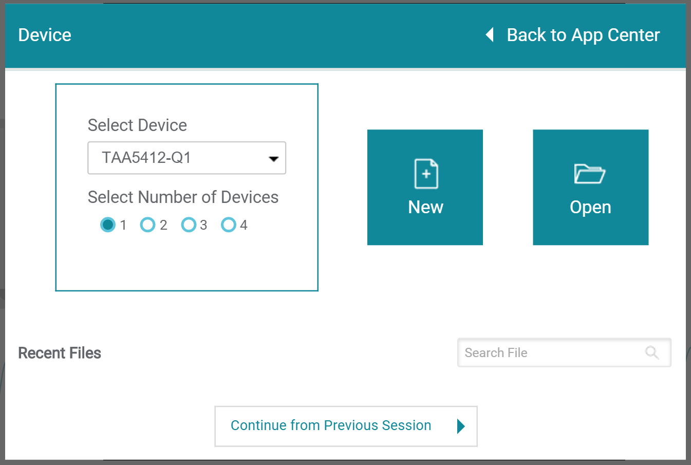
GUID-20230819-SS0I-HQRR-6HTG-TLPSMVPZCHT6-low.pngFigure 3-4 Select Device Configuration

The GUI opens to the default Device Config tab as shown below.
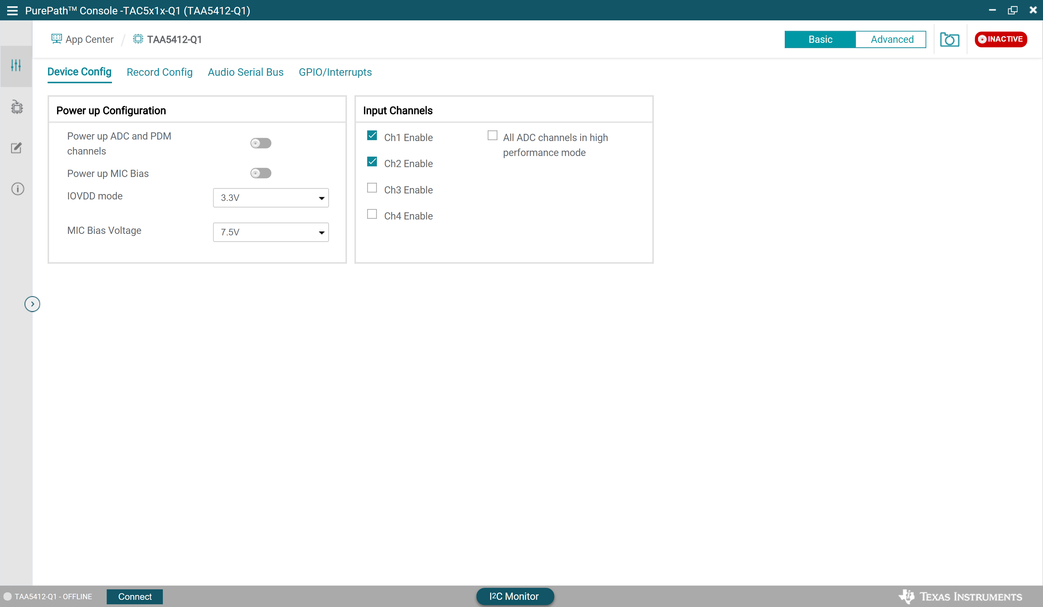
GUID-20230819-SS0I-Q6CH-3K4Q-VBM9MZQSRXP2-low.pngFigure 3-5 Device Config Tab

Before changing any parameters, check the lower left corner of the PPC3 window, as shown in Figure 3-6, to verify that the EVM is connected. If no EVM is detected, the text reads TAA5412-Q1 - OFFLINE. If the EVM is detected but does not connect automatically, a Connect button is shown. Clicking this button connects the hardware.

GUID-20230819-SS0I-GXF3-TX5J-9XV74DQNQZFW-low.pngFigure 3-6 Hardware Connect Button

When the hardware is connected, the Connect button changes to Disconnect, and the device is ready to be configured. Choose to either update GUI with device values or overwrite device with GUI values; either selection works for initial setup.

GUID-20230819-SS0I-CLWR-CT77-TGHD056M6VGC-low.pngFigure 3-7 Update GUI-Device

To activate the GUI, hit the INACTIVE red button to change to ACTIVE green button, the GUI is now in operation. The user can configure the device, and then activate the PPC3. Once the device is activated, some controls are grayed out until the ACTIVE button is deactivated.

GUID-20230819-SS0I-FHVW-8V88-ZJCBT7HVSHRX-low.pngFigure 3-8 Activate GUI