SLAU909A September 2023 – December 2023 ULC1001
4 What's in the Box
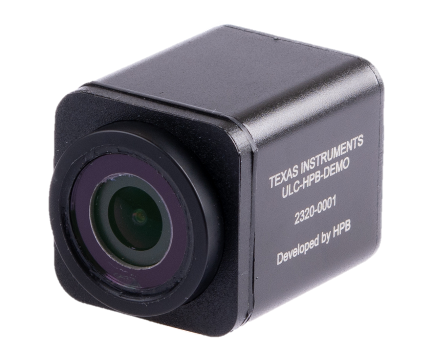
The Camera Module contains three circuit boards. From front to back, these boards are the camera module, the driver board, and a connector board for passing all signals. The device has two ports on the back: one Micro-USB for the camera and one USB-C for passing power and Inter-Integrated Circuit (I2C) communication to the driver board. The Micro-USB can optionally be connected to a Windows 10 PC. ULC-HPB-DEMO can run on the native Windows Camera app without downloading and installing additional software. The USB-C needs to be connected to the Switch Box.
 Figure 4-1 Camera Module
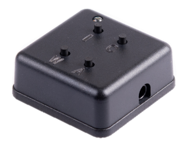
The switch box controls the ultrasonic lens cleaning in the camera module. The barrel jack plugs into the supplied switching adapter. The USB-C output plugs into the camera module.
 All high voltage is enclosed
in the camera module.
 Figure 4-2 Switch Box
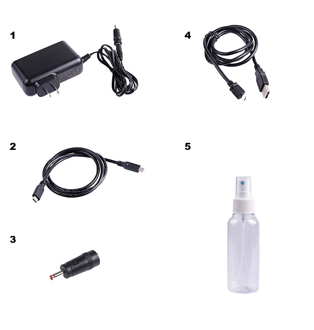
The additional hardware includes:
- Switching power supply, 36W power adapter accepts 110-240 VAC 50/60 Hz
- USB-C Cable - connects the Camera Module and the Switch Box
- Barrel jack adapter for the power supply
- USB-A to Micro USB-B Cable
- Empty spray bottle
 Figure 4-3 Additional Hardware