SLAU915 May 2024 ULC1001
- 1
- Description
- Get Started
- Features
- 5
- 1Evaluation Module Overview
- 2Hardware
-
3Software
- 3.1 GUI Setup
- 3.2 System Overview
- 3.3
GUI Overview
- 3.3.1 GUI Top Level Layout
- 3.3.2 High Level Page
- 3.3.3 Register Map Page
- 3.3.4 I2C Configuration Page
- 3.3.5 GUI Functions
- 4Hardware Design Files
- 5Additional Information
3.3.2.4 Power and Diagnostic Settings
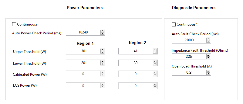
Texas Instruments created two additional modes to regulate the power delivered to the LCS, identify the faults of LCS, and check for an open load condition on the output. Refer to Section 3.2.5 for more details on the diagnostic modes.
The Power mode consists of two bursts (20 and 21). Burst 20 corresponds to Power Region 1, which is calibrated using Cal Region 1. Burst 21 corresponds to Power Region 2, which is calibrated using Cal Region 2. For convenience, the calibrated power values appear in the Power Parameters section of the GUI shown on the right side of Figure 4-18. The remaining settings are described in the Table 4-14.
The System Fault mode is a single burst which corresponds to Cal Region System Fault. The settings available for this mode are shown on the left side of Figure 4-18 and described in the Table 4-15.

Figure 3-18 Power and Diagnostic Settings
| Parameter | Description |
|---|---|
| Continuous? Check Box | Enables continuous power checks to run automatically without setting the USER_Commands_flag_newCommand at the specified period when the device is in the active power mode. PWR_CTL = 0x00 |
| Auto Power Check Period | Time interval used when Continuous Power mode is enabled |
| Region 1 Upper Threshold | Upper power threshold for Region 1 |
| Region 1 Lower Threshold | Lower power threshold for Region 1 |
| Region 2 Upper Threshold | Upper power threshold for Region 2 |
| Region 2 Lower Threshold | Lower power threshold for Region 2 |
| Parameter | Description |
|---|---|
| Continuous? Check Box | Enables continuous diagnostic checks to run automatically without setting the USER_Commands_flag_newCommand at the specified period when the device is in the active power mode. PWR_CTL = 0x00. |
| Auto Fault Check Period | Time interval used when Continuous Diagnostic mode is enabled. |
| Impedance Fault Threshold | Threshold for determining a fault in the LCS. |
| Open Load Threshold | Current threshold for detecting an open load condition. |