SLAU915 May 2024 ULC1001
- 1
- Description
- Get Started
- Features
- 5
- 1Evaluation Module Overview
- 2Hardware
-
3Software
- 3.1 GUI Setup
- 3.2 System Overview
- 3.3
GUI Overview
- 3.3.1 GUI Top Level Layout
- 3.3.2 High Level Page
- 3.3.3 Register Map Page
- 3.3.4 I2C Configuration Page
- 3.3.5 GUI Functions
- 4Hardware Design Files
- 5Additional Information
3.3.2.2 Calibration Settings
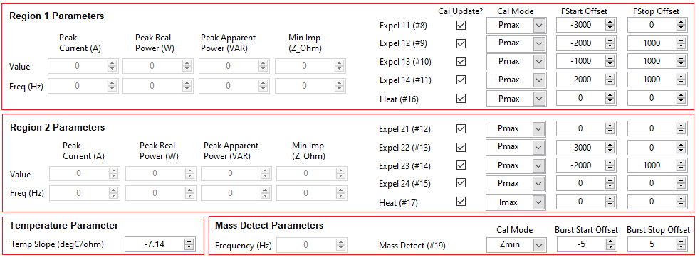
When the ULC1001-DRV2911 EVM is connected and powered, run Calibration Mode first. The ULC1001 Calibration mode measures multiple electrical parameters such as impedance, real and apparent power, and the current magnitude for programmed frequency ranges. These measurements are used to setup cleaning modes, temperature protection, power monitoring, mass detection, and diagnostics. Refer to Section 3.2.3 for details on the calibration bursts. The calibration mode sequence is shown in Figure 4-14. The calibration parameters and settings are shown in Figure 4-15. See Section 3.3.5.5 for a step-by-step tutorial on configuring the Calibration Mode settings and running Calibration.

Figure 3-14 Calibration Mode Sequence
For good calibration, the enumerated calibration sequence is as follows:
- 0 - CONTROL_Burst_Cal_DcBias
- 5 - CONTROL_Burst_Cal_Region_Temp
- 1 - CONTROL_Burst_Cal_Region_MassDetect
- 2 - CONTROL_Burst_Cal_Region_1
- 3 - CONTROL_Burst_Cal_Region_2

Figure 3-15 Calibration Settings and Parameters
Refer to the Section 3.2.3.2 for details on the temperature slope setting.
| Parameter | Description |
|---|---|
| Temperature Slope [°C / Ω] | LCS temperature estimation algorithm slope; provided by TI for provided LCS in ULC1001-DRV2911 EVM kit contents. |
The region parameters are returned after running the Region 1 and Region 2 calibration sequences. The registers linked to these fields are USER_Params_baselineParams, where the suffix describes the parameter. Each region parameter has an associated frequency that is used for updating the cleaning mode bursts based on the Cal Mode setting on the right side of the calibration settings page. These parameters are peak current, peak real power, peak apparent power, and minimum impedance described in Table 4-10. All region parameters are returned regardless of the Cal Mode setting, but only the frequency used in the Cal Mode setting is used for the calibration algorithm. These Cal Mode settings are listed below:
- USER_Params_controlParams_calMode_8 for Clean_Expel_11 (8)
- USER_Params_controlParams_calMode_9 for Clean_Expel_12 (9)
- USER_Params_controlParams_calMode_10 for Clean_Expel_13 (10)
- USER_Params_controlParams_calMode_11 for Clean_Expel_14 (11)
- USER_Params_controlParams_calMode_12 for Clean_Expel_21 (12)
- USER_Params_controlParams_calMode_13 for Clean_Expel_22 (13)
- USER_Params_controlParams_calMode_14 for Clean_Expel_23 (14)
- USER_Params_controlParams_calMode_15 for Clean_Expel_24 (15)
- USER_Params_controlParams_calMode_16 for Heat_Region_1 (16)
- USER_Params_controlParams_calMode_17 for Heat_Region_2 (17)
- USER_Params_controlParams_calMode_19 for massDetect (19)
| Cal Mode | Description |
|---|---|
| Imax | Maximum current magnitude in the region. |
| Pmax | Maximum real power in the region. |
| Smax | Maximum apparent power in the region. |
| Zmin | Minimum impedance magnitude in the region. |
The two columns, F Start Offset and F Stop Offset, hold the frequency offset values for the calibration algorithm. Bursts 8-17 are updated based on the frequency values. Since Burst 19 is an active burst, the start and stop frequencies are updated based on an integer Burst Offset value. Therefore, Burst 19 is updated based on the calibrated frequency value ±Delta_Freq*n, where Delta_Freq = Fs/N and n is an integer.
As stated previously, the Region 1 calibration burst (2) updates cleaning bursts 8-11 and heating burst 16 and the Region 2 calibration burst (3) updates cleaning bursts 12-15 and heating burst 17. When running calibration, only the cleaning and heating bursts of which control bits are enabled are updated. This allows for only specific bursts to be updated in a re-running of calibration, opposed to all bursts for the region. In the GUI, these can be enabled / disabled with the check box below Cal Update?. These enable settings are also listed below:
- USER_Params_Update_Expel_11 for Region 1 Clean_Expel_11 (8)
- USER_Params_Update_Expel_12 for Region 1 Clean_Expel_12 (9)
- USER_Params_Update_Expel_13 for Region 1 Clean_Expel_13 (10)
- USER_Params_Update_Expel_14 for Region 1 Clean_Expel_14 (11)
- USER_Params_Update_Expel_21 for Region 2 Clean_Expel_21 (12)
- USER_Params_Update_Expel_22 for Region 2 Clean_Expel_22 (13)
- USER_Params_Update_Expel_23 for Region 2 Clean_Expel_23 (14)
- USER_Params_Update_Expel_24 for Region 2 Clean_Expel_24 (15)
- USER_Params_Update_Heat_Region_1 for Region 1 Heat_Region_1 (16)
- USER_Params_Update_Heat_Region_2 for Region 2 Heat_Region_2 (17)