SLAU915 May 2024 ULC1001
- 1
- Description
- Get Started
- Features
- 5
- 1Evaluation Module Overview
- 2Hardware
-
3Software
- 3.1 GUI Setup
- 3.2 System Overview
- 3.3
GUI Overview
- 3.3.1 GUI Top Level Layout
- 3.3.2 High Level Page
- 3.3.3 Register Map Page
- 3.3.4 I2C Configuration Page
- 3.3.5 GUI Functions
- 4Hardware Design Files
- 5Additional Information
3.3.2.1 Burst Parameters
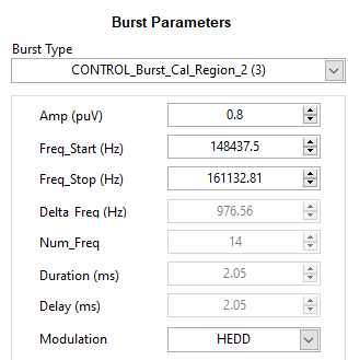
The Burst Parameter section always displays the 8 configurable burst parameters for the selected mode. A drop-down menu can be used to see the available burst for each tab in the High Level Page. Active and Passive bursts have certain parameters that must be set to specific values for TI's algorithms to run properly. The Burst Parameters section of the GUI is shown in Figure 4-11.
Active bursts enable the IV sense path (0-5, 19-23) and Passive bursts do not enable the IV sense path (6-17). Burst 18 is an Idle burst, which is returned to automatically at the end of each mode; this burst is never set by the user. Each burst contains the following eight parameters: Amp, Delay, Duration, Freq_Start, Freq_Stop, Num_Freq, Delta_Freq, and Modulation.
All Active bursts frequency settings, except burst 0, must follow the following: Delta_Freq*n = (Fs/N)*n = (ULC_RX_mode_cfg bits [0-4]/USER_Params_numSamples)*n, where n is an integer multiplier. Freq_start ≤ Freq_stop. Freq_start and Freq_stop must be integer multiples of Delta_Freq. Table 4-7 shows the settings for Active Burst Parameters. Figure 4-12 shows a depiction of how an active burst is run.
All Passive bursts must have Num_Freq = 0. For a Passive burst, the frequency sweeps from Fstart to Fstop at a rate of Delta_Freq/ISR rate. When Fstart = Fstop, Delta_Freq must be set to 0Hz. Table 4-8 shows the settings for Passive Burst Parameters. Figure 4-13 shows a depiction of how passive bursts are run.
 Figure 3-11 Burst Parameters
 Figure 3-12 Active Burst Example
| Burst Parameter | Description |
|---|---|
| Amp [puV] | Burst excitation duty cycle that drives the LCS defined in PerUnit Value from 0 to 1. Chosen by user. |
| Freq_Start [Hz] | Start of frequency content in burst. Freq_start ≤ Freq_stop. Chosen by user. Auto-snap to valid value by GUI. |
| Freq_Stop [Hz] | Stop of frequency content in burst. Freq_stop ≥ Freq_start. Chosen by user. Auto-snap to valid value by GUI. |
| Delta_Freq [Hz] | Delta frequency for each frequency step between Freq_Stop and Freq_Start. GUI default is always 976.56Hz for ULC1001-DRV2911 EVM. Delta_Freq = Fs/N. Auto-updated by GUI. |
| Num_Freq | Equals ((Freq_Stop - Freq_Start)/Delta_Freq) +1. Auto-updated by GUI. |
| Duration [ms] | Duration for which each excitation frequency drives the LCS. Duration must equal USER_Params_numStages +1 (default is 2 ISR periods, 2ms). Auto-updated by GUI. |
| Delay [ms] | The additional delay placed at the end of each frequency step between Freq_Start and Freq_Stop. |
| Modulation | Changes modulation method between Direct Drive and standard AD modulation. AD modulation uses a carrier frequency that is 10 times the programmed frequency. |
 Figure 3-13 Passive Burst Example
| Burst Parameter | Description |
|---|---|
| Amp [puV] | Burst excitation duty cycle that drives the LCS defined in PerUnit Value from 0 to 1. Chosen by user. |
| Freq_Start [Hz] | Start of frequency content in burst. Freq_start ≤ Freq_stop. Auto updated after calibration. |
| Freq_Stop [Hz] | Stop of frequency content in burst. Freq_stop ≥ Freq_start. Auto updated after calibration. |
| Delta_Freq [Hz] | Delta frequency is the change in frequency per the ISR time step. If Fstart = Fstop, then set Delta_Freq = 0. GUI default is 40Hz for ULC1001-DRV2911 EVM. |
| Num_Freq | For Passive bursts, Num_Freq = 0. |
| Duration [ms] | Duration for each excitation frequency drives the LCS. GUI default is 98 ISR periods, 100ms for ULC1001-DRV2911 EVM. |
| Delay [ms] | The additional delay placed at the end of the burst. |
| Modulation | Changes modulation method between Direct Drive and standard AD modulation. AD modulation uses a carrier frequency that is 10 times the programmed frequency. |