SLAU915 May 2024 ULC1001
- 1
- Description
- Get Started
- Features
- 5
- 1Evaluation Module Overview
- 2Hardware
-
3Software
- 3.1 GUI Setup
- 3.2 System Overview
- 3.3
GUI Overview
- 3.3.1 GUI Top Level Layout
- 3.3.2 High Level Page
- 3.3.3 Register Map Page
- 3.3.4 I2C Configuration Page
- 3.3.5 GUI Functions
- 4Hardware Design Files
- 5Additional Information
3.2.4 System Cleaning
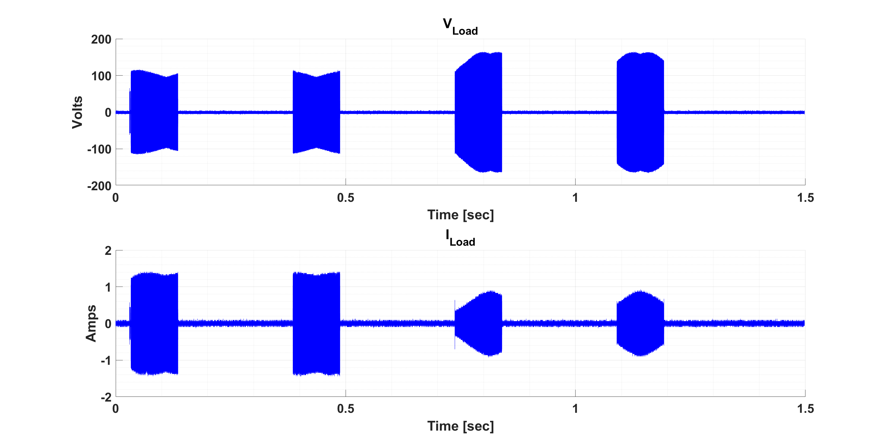
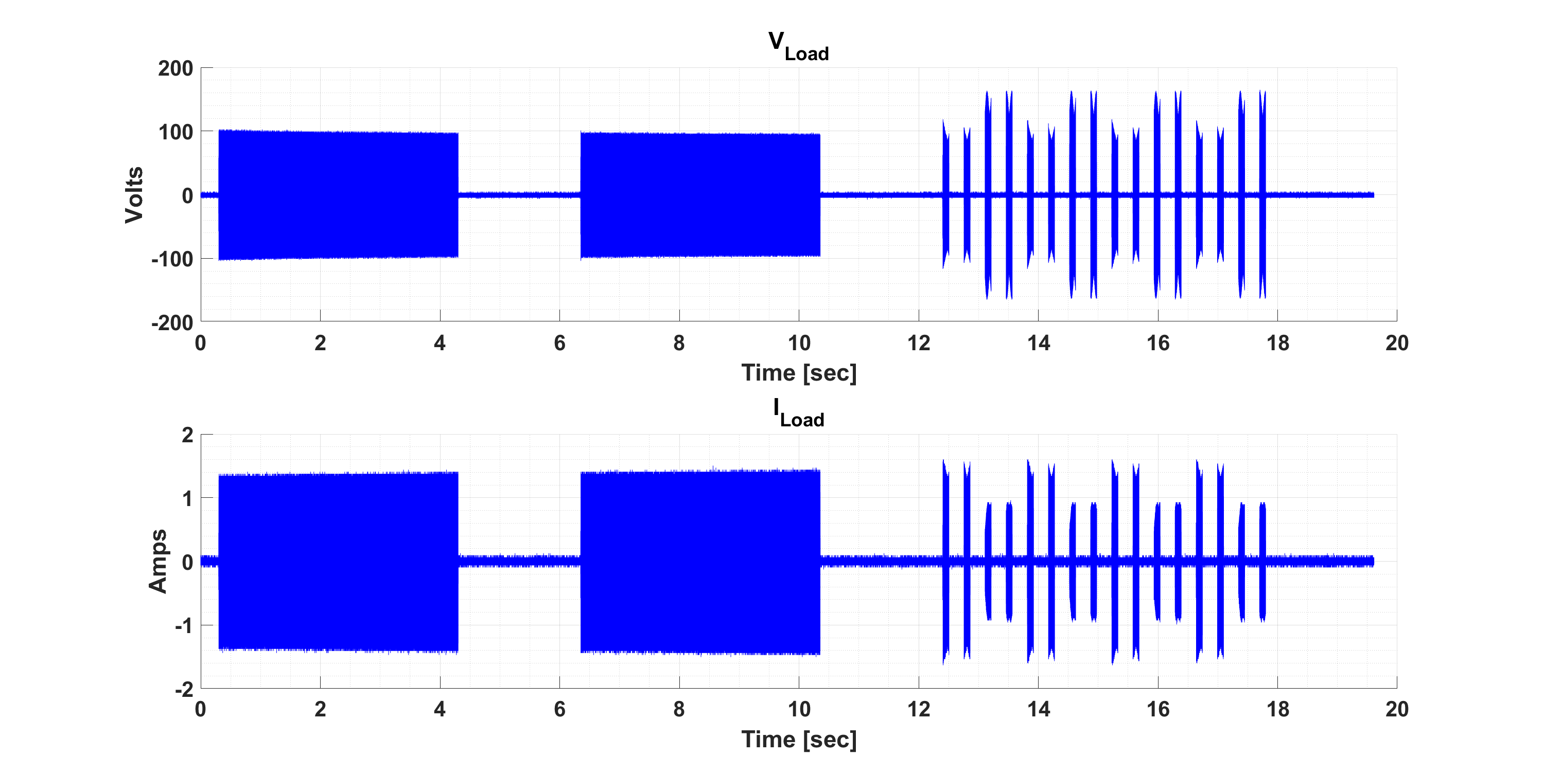
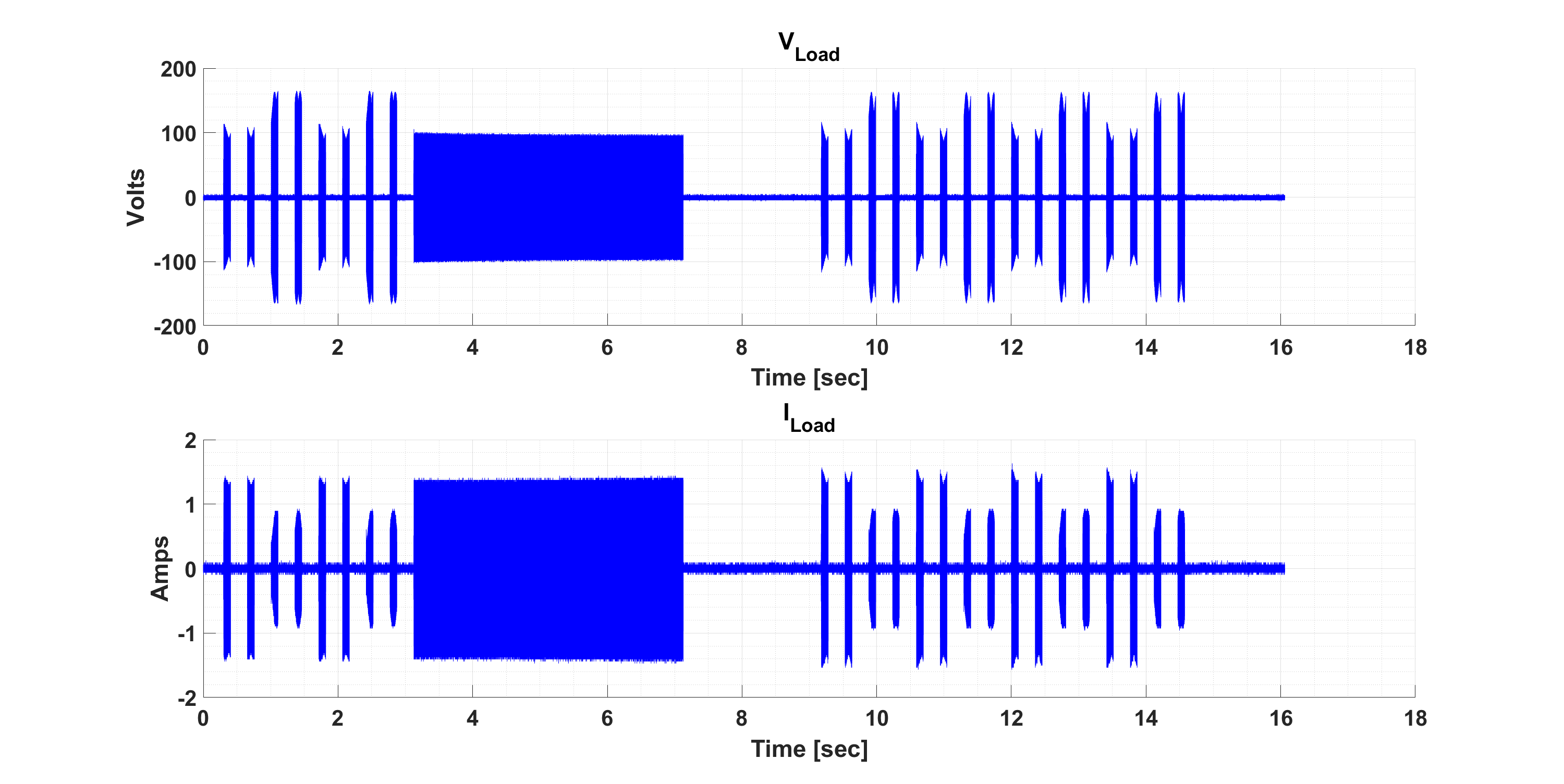
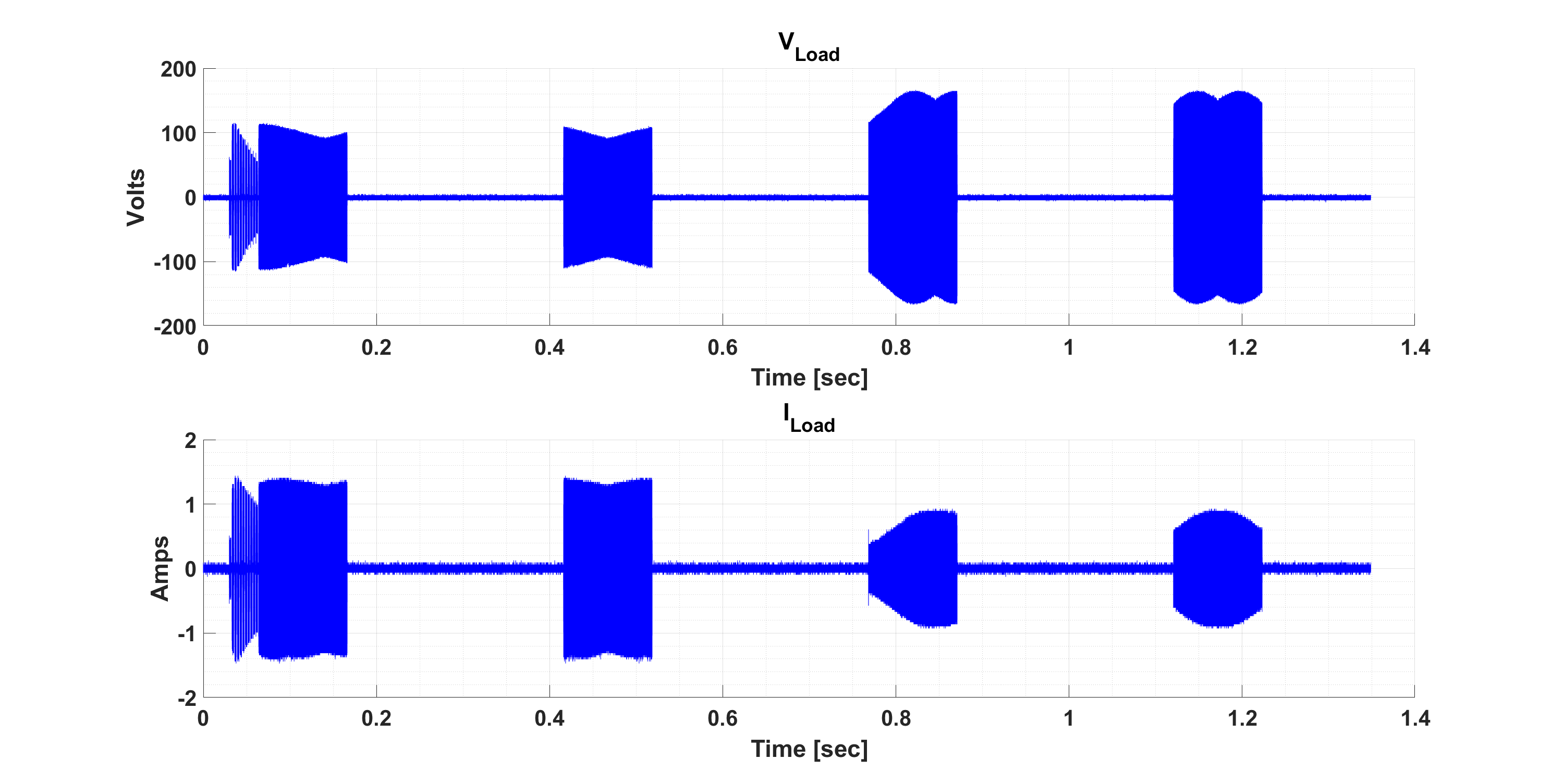
Texas Instruments created three main cleaning modes for removing ice, mud, and water from the lens of the LCS and an Auto mode that can be programmed to drive a cleaning sequence when mass, such as water, is detected on the lens. Two additional custom modes are also available for flexibility. The valid bursts for cleaning modes are listed in Table 4-4. As a reference, scope voltage and current waveform captures for each type of cleaning mode are depicted in the following figures: Figure 4-4, Figure 4-5, Figure 4-6, and Figure 4-7.
| Burst # | Burst Name | Description |
|---|---|---|
| 6 | CONTROL_Burst_Clean_Custom_1 | Custom bursts that are not updated after calibration is run. |
| 7 | CONTROL_Burst_Clean_Custom_2 | |
| 8 | CONTROL_Burst_Clean_Expel_11 | Burst start and stop frequencies are updated after running Calibration Region 1 burst. Different offset frequencies can be set prior to calibration. |
| 9 | CONTROL_Burst_Clean_Expel_12 | |
| 10 | CONTROL_Burst_Clean_Expel_13 | |
| 11 | CONTROL_Burst_Clean_Expel_14 | |
| 12 | CONTROL_Burst_Clean_Expel_21 | Burst start and stop frequencies are updated after running Calibration Region 2 burst. Different offset frequencies can be set prior to calibration. |
| 13 | CONTROL_Burst_Clean_Expel_22 | |
| 14 | CONTROL_Burst_Clean_Expel_23 | |
| 15 | CONTROL_Burst_Clean_Expel_24 | |
| 16 | CONTROL_Burst_Heat_Region_1 | Long bursts used for heating sequences. Burst start and stop frequencies are updated after running Calibration Region 1 and 2 bursts. |
| 17 | CONTROL_Burst_Heat_Region_2 | |
| 19 | CONTROL_Burst_MassDetect | Active burst that invokes the mass detection algorithm. Burst start and stop frequencies are updated after running Calibration MassDetect burst. |
| 23 | CONTROL_Burst_Temp | Active burst that invokes the temperature protection algorithm. Burst frequency and amplitude must match the Temp Calibration settings. Temperature protection can also run continuously without setting this burst. |
The Auto Cleaning Mode cleans water from the LCS lens when water is detected. CONTROL_Burst_MassDetect (19) makes the Auto Cleaning Mode possible. As shown in Figure 4-7, the MassDetect burst (19) is placed before the water and de-ice bursts (23, 16, 8, 9, 13, 14). Auto mode uses CONTROL_Burst_MassDetect to test whether the LCS has additional mass (for example, water) on the lens or not. If mass is detected, then the remaining bursts in Auto mode are run.
CONTROL_Burst_Temp (23) can be enabled using the Enable Temp checkbox, refer to Table 4-13, and runs continuously on a periodic time interval. When running continuously, the Temp burst interrupts any passive bursts to check the LCS temperature. Once the temperature is measured and below the OverTemp Threshold, the mode continues to run from the interrupted location. This allows the ULC1001-DRV2911 EVM to monitor the temperature of the LCS and prevent an overtemperature condition. This burst can also be added to the Auto Cleaning Mode sequence described in the above paragragh. The Temp burst (23) followed by a heating burst (16 or 17) can be added after the MassDetect burst (19) to integrate auto de-icing. Calibration mode must be run first to calibrate the Temp burst. See Section 3.3.2.1 for details on how to set the temperature threshold through the ULC1001 GUI.
The predefined cleaning modes must be used for initial experiments. Each cleaning mode has settings that can be adjusted to improve the cleaning performance. For the most design freedom, two custom modes are also supported. Additionally, there are two custom bursts (6, 7) that are not affected by calibration. The settings for all cleaning modes are described in Section 3.3.2.3.
 Figure 3-4 Water Cleaning LCS Voltage & Current
  Figure 3-5 Deice Cleaning LCS Voltage & Current
 Figure 3-6 Mud Cleaning LCS Voltage & Current
  Figure 3-7 Auto Cleaning LCS Voltage & Current