SLAU927A March 2024 – June 2024 MSPM0G3507
- 1
- Abstract
- Trademarks
- 1Introduction
-
2Hardware Setup
- 2.1 EVM Hardware Setup
- 2.2 Pin Configurations for IPD Usage
- 2.3 Pin Configurations for PWM Outputs
- 2.4 Pin Configurations for ADC Currents
- 2.5 Pin Configurations for ADC Voltages
- 2.6 Pin Configurations for Faults
- 2.7 Pin Configurations for GPIO Output Functions
- 2.8 Pin Configurations for SPI Communication
- 2.9 Pin Configurations for UART Communication
- 2.10 External Connections for Evaluation Boards
- 3Software Setup
- 4GUI Setup
- 5Register Map
- 6Basic Tuning
-
7Advanced Tuning
- 7.1
Control Configurations Tuning
- 7.1.1 Initial Speed Detection of the Motor for Reliable Motor Resynchronization
- 7.1.2 Unidirectional Motor Drive Detecting Backward Spin
- 7.1.3 Preventing Back Spin of Rotor During Startup
- 7.1.4 Gradual and Smooth Start up Motion
- 7.1.5 Faster Startup Timing
- 7.1.6 Stopping Motor Quickly
- 7.1.7 Flux Weakening : Operating Motor at Speeds Higher than Rated Speed
- 7.1.8 Maximum Torque Per Ampere : Improve Efficiency of IPMSM Motors
- 7.1.9 Preventing Supply Voltage Overshoot During Motor Stop.
- 7.1.10 Protecting the Power Supply
- 7.1.11 FOC Bandwidth Selection
- 7.1
Control Configurations Tuning
- 8Hardware Configurations
- 9Revision History
4 GUI Setup
The user can optionally use the MSPM0 Sensorless FOC GUI as a host to send commands to the MSPM0 MCU at the target to control the motor using serial to UART interface.
The GUI contains a USB-to-UART codec that can send UART commands as a host to the MSPM0 LaunchPad kit. The application software includes a configurable UART register map and data format that translates the UART data into simplified motor control commands.
| Connection | Interface | Hardware Connections |
|---|---|---|
| GUI to target MSPM0 MCU | UART | UART3_TX, UART3_RX |
To launch the GUI, go to the MSPM0 Sensorless FOC GUI. page.
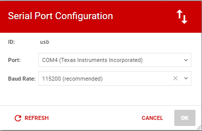
Serial Port Configuration
Configure the serial port based on the connected port to the PC and configure the Baud rate as 115200.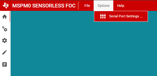
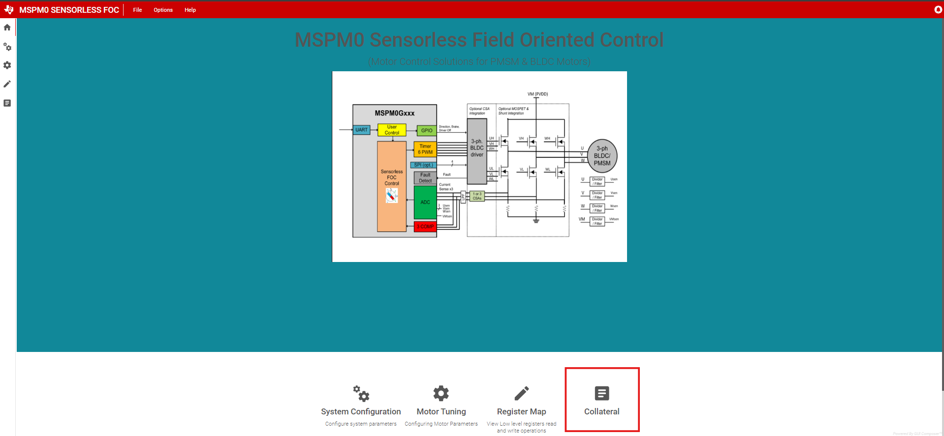
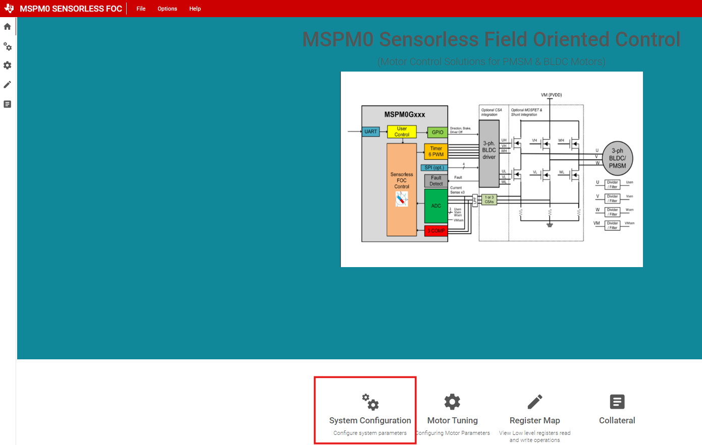
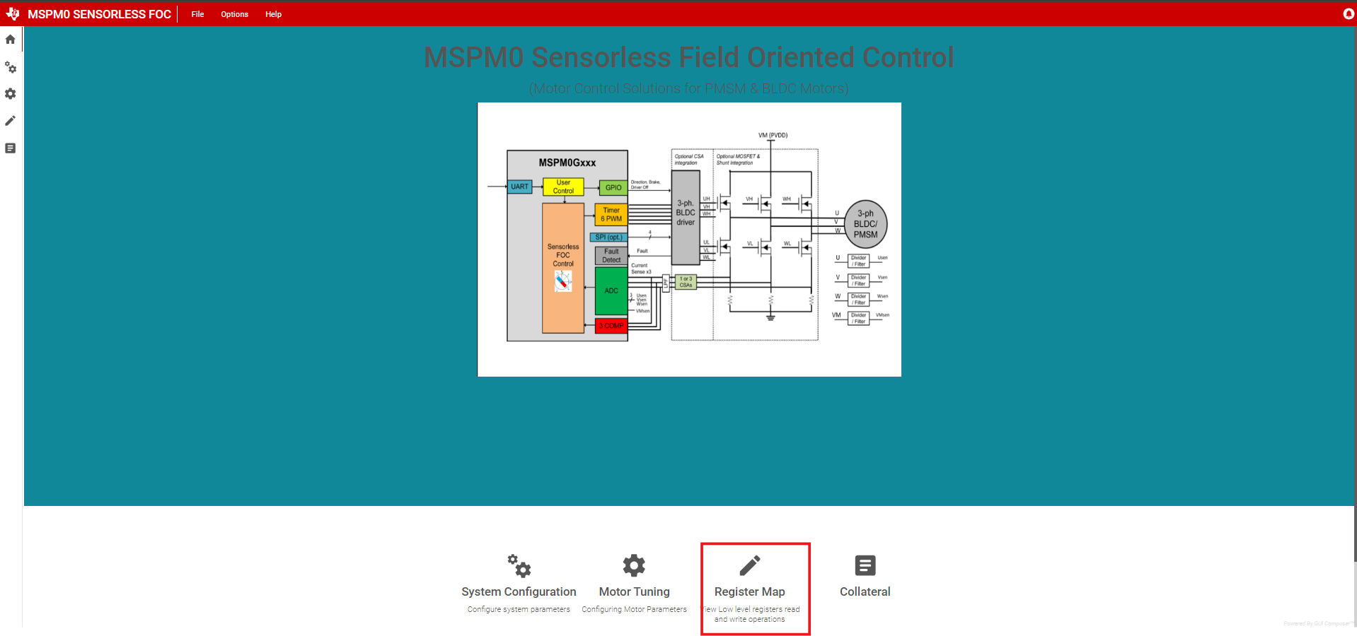
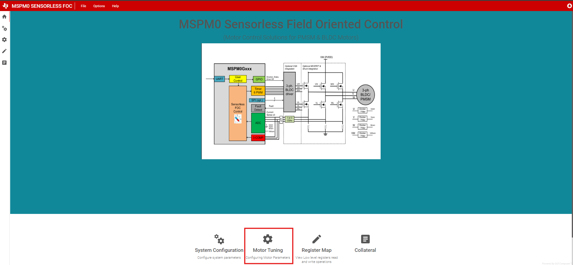
GUI Home Page
Below is the GUI home page from which user can navigate to various windows for specific configurations.System Configurations
User can set the basic configurations of Motor and EVM system parameters from the system configuration page
Register Map
Register Map page contains the configurations for all the available Motor Tuning parameters which can be configured before starting the Motor. Register map page also contains the Status variables which can be continuously monitored.
Motor Tuning Page
User can set the speed command and monitor the motor status and fault variables from this window.
Collateral Page
This page holds the links to various user guides to set up the software and migrate to different platforms.