SLAU944 August 2024 TAS2320
- 1
- Description
- Get Started
- Features
- Applications
- 6
- 1Evaluation Module Overview
- 2Quick Start Guide
-
3Hardware
- 3.1 AC-MB Settings
- 3.2 AC-MB Power Supply
- 3.3 Default Jumper Setting on TAS2320EVM
- 3.4 I2C Target Address Selection
- 3.5 IOVDD Power Supply Options
- 3.6 AVDD Power Supply Options
- 3.7 VBAT Power Supply Options
- 3.8 PVDD Power Supply Options
- 3.9 IOVDD_BUFF Power Supply Options
- 3.10 Speaker Outputs
- 3.11 2-Channel Configuration
- 3.12 4-Wire Measurement of Load
- 4Hardware Design Files
- 5Additional Information
3.1.3 External Audio AC-MB Settings
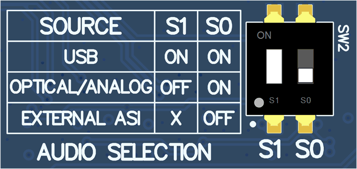
In this mode, the audio serial interface clocks for the evaluation board are provided through connector J7 from an external source. This architecture allows the use of an external system to communicate with the evaluation board, such as a different host processor or test equipment (for instance, Audio Precision PSIA). The clocks generated from the USB interface and PCM9211 are isolated with this setting. The AC-MB audio setting for the external mode of operation is shown in Figure 3-3.
 Figure 3-3 AC-MB External Audio
Setting
Figure 3-3 AC-MB External Audio
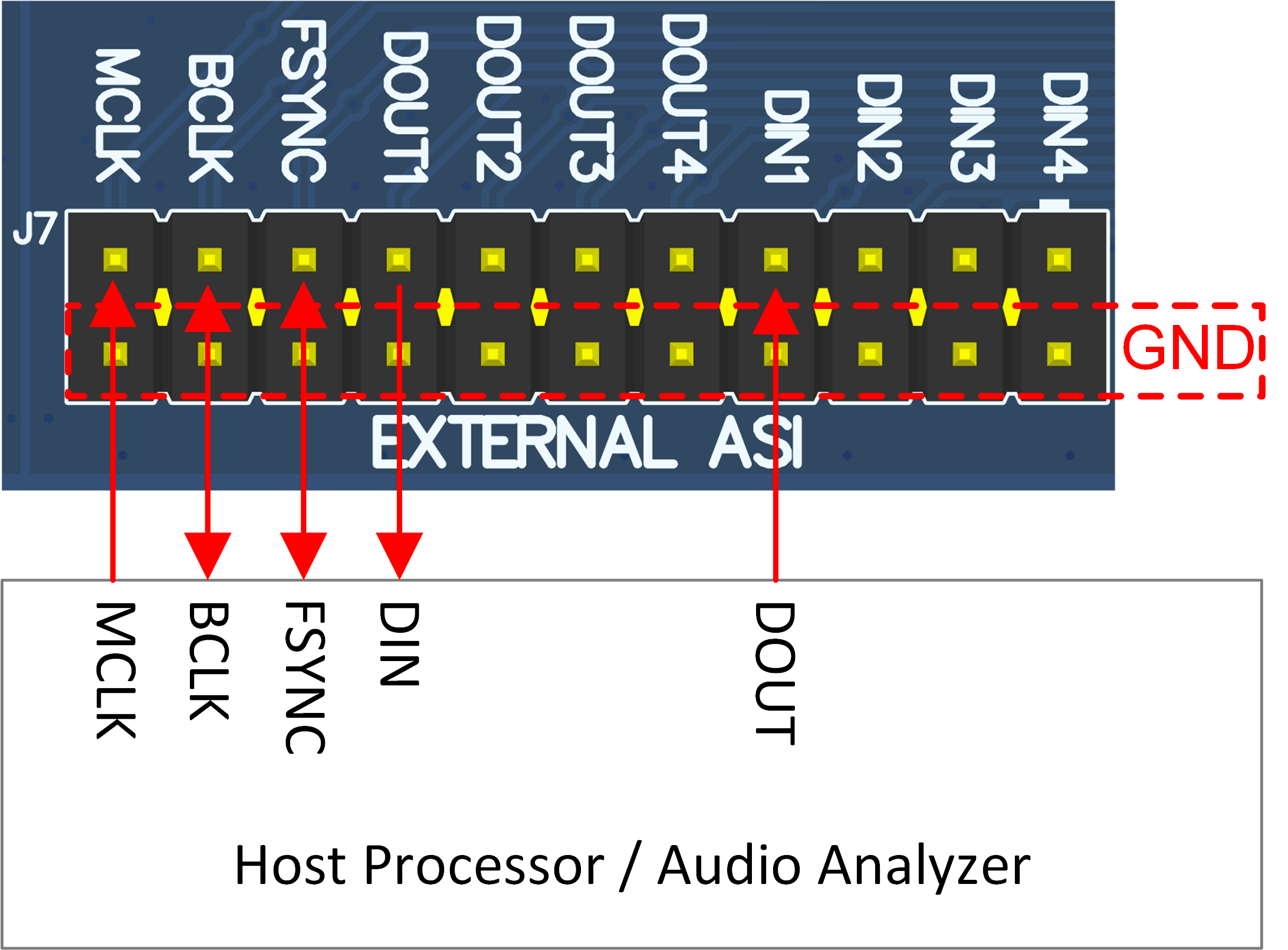
SettingHow to connect the external audio interface with the bottom row for the ground and the top row for signals is shown in Figure 3-4.
 Figure 3-4 AC-MB Connection with External
Audio Serial Interface