SLAU944 August 2024 TAS2320
- 1
- Description
- Get Started
- Features
- Applications
- 6
- 1Evaluation Module Overview
- 2Quick Start Guide
-
3Hardware
- 3.1 AC-MB Settings
- 3.2 AC-MB Power Supply
- 3.3 Default Jumper Setting on TAS2320EVM
- 3.4 I2C Target Address Selection
- 3.5 IOVDD Power Supply Options
- 3.6 AVDD Power Supply Options
- 3.7 VBAT Power Supply Options
- 3.8 PVDD Power Supply Options
- 3.9 IOVDD_BUFF Power Supply Options
- 3.10 Speaker Outputs
- 3.11 2-Channel Configuration
- 3.12 4-Wire Measurement of Load
- 4Hardware Design Files
- 5Additional Information
3.1.1 Audio Serial Interface Settings
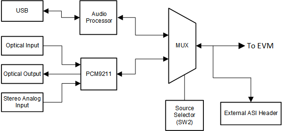
The AC-MB provides the digital audio signals to the evaluation module from the USB, optical connector, stereo jack, and external audio serial interface (ASI) header. The block diagram of the ASI routing on the AC-MB is shown in Figure 3-1.
 Figure 3-1 AC-MB Audio Serial Interface Routing
Switch SW2 on the AC-MB selects the audio serial bus that interfaces with the TAS2320EVM daughter card. Next to switch SW2, the AC-MB has a quick reference table to identify the audio serial interface source options and switch settings. The AC-MB acts as the controller for the audio serial interface, with three different modes of operation: USB, optical or analog, or external ASI.