SLAU948 October 2024 MSPM0G3507
- 1
- Abstract
- Trademarks
- 1Introduction
-
2Hardware Setup
- 2.1 EVM Hardware Setup
- 2.2 Pin Configurations for PWM Outputs
- 2.3 Pin Configurations for ADC Currents
- 2.4 Pin Configurations for ADC Voltages
- 2.5 Pin Configurations for Hall Sensor Inputs Through GPIO
- 2.6 Pin Configurations for Faults
- 2.7 Pin Configurations for GPIO Output Functions
- 2.8 Pin Configurations for SPI Communication
- 2.9 Pin Configurations for UART Communication
- 2.10 External Connections for Evaluation Boards
- 3Software Setup
- 4GUI Setup
-
5Register Map
- 5.1 Register Map Page in GUI
- 5.2
User Control Registers (Base Address = 0x20200400h)
- 5.2.1 Speed Control Register (Offset = 0h) [Reset = 00000000h]
- 5.2.2 Algo Debug Control 1 Register (Offset = 4h) [Reset = 00000000h]
- 5.2.3 Algo Debug Control 2 Register (Offset = 8h) [Reset = 00000000h]
- 5.2.4 Algo Debug Control 3 Register (Offset = Ch) [Reset = 00000000h]
- 5.2.5 DAC Configuration Register (Offset = 10h) [Reset = 00000000h]
- 5.3
User Input Registers (Base Address = 0x20200000h)
- 5.3.1 SYSTEM_PARAMETERS (Offset = 0h)
- 5.3.2 MOTOR_STARTUP1 Register (Offset = 3Ch) [Reset = 00000000h]
- 5.3.3 MOTOR_STARTUP2 Register (Offset = 40h) [Reset = 00000000h]
- 5.3.4 CLOSED_LOOP1 Register (Offset = 44h) [Reset = 00000000h]
- 5.3.5 CLOSED_LOOP2 Register (Offset = 48h) [Reset = 00000000h]
- 5.3.6 FIELD_CTRL Register (Offset = 4Ch) [Reset = 00000000h]
- 5.3.7 FAULT_CONFIG1 Register (Offset = 50h) [Reset = 00000000h]
- 5.3.8 FAULT_CONFIG2 Register (Offset = 54h) [Reset = 00000000h]
- 5.3.9 MISC_ALGO Register (Offset = 58h) [Reset = 00000000h]
- 5.3.10 PIN_CONFIG Register (Offset = 5Ch) [Reset = 00000000h]
- 5.3.11 PERI_CONFIG Register (Offset = 60h) [Reset = 00000000h]
- 5.4 User Status Registers (Base Address = 0x20200430h)
- 6Basic Tuning
-
7Advanced Tuning
- 7.1
Control Configurations Tuning
- 7.1.1 Control Mode of Operation
- 7.1.2 Closed Loop Torque Control Mode
- 7.1.3 Closed Loop Power Control Mode
- 7.1.4 Closed Loop Speed Control Mode
- 7.1.5 Voltage Control Mode
- 7.1.6 Stopping Motor Quickly
- 7.1.7 Flux Weakening: Operating Motor at Speeds Higher Than Rated Speed
- 7.1.8 Maximum Torque Per Ampere : Improve Efficiency of IPMSM Motors
- 7.1.9 Preventing Supply Voltage Overshoot During Motor Stop.
- 7.1.10 Protecting the Power Supply
- 7.1.11 FOC Bandwidth Selection
- 7.1
Control Configurations Tuning
- 8Hardware Configurations
6.2.1 Hall Sensor Auto Calibration
In Hall Sensor based FOC , Hall signals are used to detect the rotor position information and drive the motor efficiently. FOC application requires three digital Hall Inputs placed 60 degrees electrically connected to the GPIO's as inputs feeding the rotor position information.
User needs to populate the Hallangle table in IQ27 P.U appropriately for a given Hall Sequence with reference to Phase connections in the ISR.c file as shown in Figure 6-5.

Figure 6-5 Hall Angle Table Values
In general, the Hall placements can be erroneous and the electrical displacement can be less than or greater than 60 degrees. Any error in the hall placement results in torque ripple and non sinusoidal current. The Hall pin sequence is also significant with reference to the Motor Phase connection and the driving angle for a given phase depends on the sequence of connections. This information is typically available in data sheet.
Hall calibration eliminates need for the data sheet and corrects the hall placement error for improved current waveform in motors with erroneous hall placements.\
The above hall angle table values can be auto generated with Hall Calibration routine as described below:
Calibration Routine:
- Motor_Align: Aligning the motor to a known rotor angle is the first step in the calibration sequence. In this routine Motor aligns to CALIBRATION_ALIGN_ANGLE macro for a duration calibAlignTime set in the User Inputs Motor Startup1 parameters. Sufficient calibAlignTime is to be configured such that the motor aligns and stops movement before the calibration is initiated.
- Motor_Calib_Run: Once Align step is successfully completed, the rotor microsteps with an angle specified as in macro CALIBRATION_ANGLE_STEP for a duration of calibRunTime set in the User Inputs Motor Startup1 parameters. Motor rotates for one complete mechanical cycles (Pole_Pairs * Electrical cycles) in both forward and reverse direction to compute the average Hall angle.
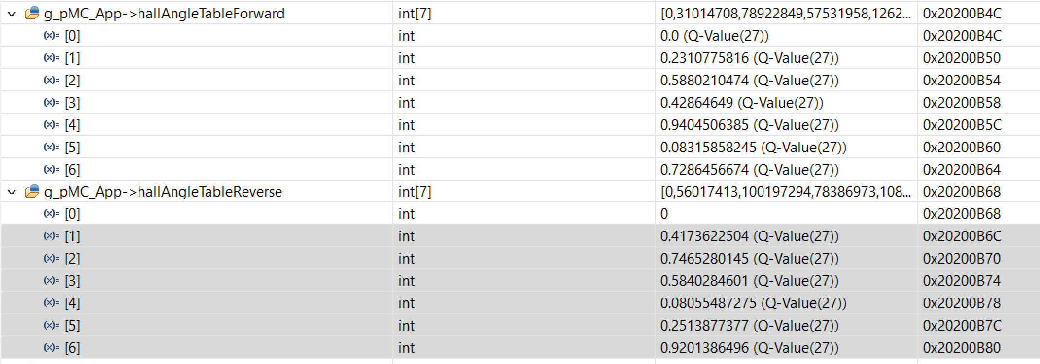
- Motor_Calib_Complete: Once motor calibration is successfully completed , rotor angle for each Hall State transitions for both Forward and Reverse directions are generated in the Hall angle tables as hallAngleTableForward and hallAngleTableReverse .
Below is the sequence to follow for the Auto Hall Sensor Calibration:
- Configure and tune the below
input parameters.
- Configure the Current loop Kp & Ki Parameters in the System parameters.
- Configure the Motor
Startup 1 parameters as below to tune the Motor Align and Motor Calib
Run States

Figure 6-6 Hall Calibration Configurations- CalibCurrLimit : Id current forced during Calibration
- calibAlignTime : Time in milli seconds applied for the CALIBRATION_ALIGN_ANGLE while aligning for the first time.
- calibRunTime: Time in milli seconds applied while micro stepping and sweeping the mechanical cycle in steps of HALL_CALIBRATION_STEP.
- CurrRampRate: Ramp rate of Id current during the first align to CALIBRATION_ALIGN_ANGLE.
- Set the Hall Sensor Calibration
Enable bit in Algo Debug Control 2 Register and set the Motor speed to non zero
value.

Figure 6-7 Hall Calibration Enable - Once the Calibration sequence is
completed, the CalibState changes to HALL_CALIB_ COMPLETE.

The Hall angle tables in the Motor Control application variables are updated as below. Angle tables are in Q27 format by default. _IQ27(1.0) corresponds to 360 degrees electrical cycle.
Figure 6-8 Hall Calib Complete
Figure 6-9 Generated Hall Angle Table - Once
satisfactory Calibration routine is performed such that the Motor Spins smoothly
in closed loop operation, user can store these calibrated angle values in the
forwardHallIndexLUT & reverseHallIndexLUT defined in ISR.c. Upon
MCU restart the values from these LUT’s are used by default for spinning the
motor.

Figure 6-10 Updated Hall Angle Table