SLLA497 September 2020 TMS320F28P550SJ , TMS320F28P559SJ-Q1
4.3 LLC Resonant Converter
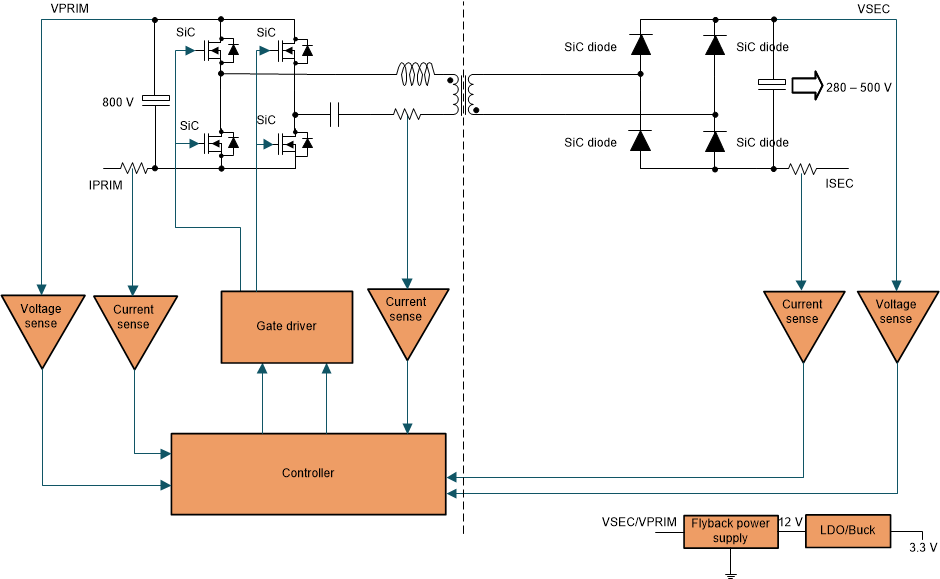
The gain of this converter is a function of switching bridge gain, resonant tank gain and transformer turns ratio. The output voltage regulation is achieved by varying the switching frequency of operation. There are three modes/regions of operation in the LLC resonant converter namely the operation at resonant frequency, above resonant frequency and below resonant frequency. During below resonant frequency operation, the resonant half cycle inductor current reaches the value of magnetizing current within the switching cycle and leads to soft switching across secondary rectifier diodes but on the other hand leads to more conduction losses due to more circulating energy. Above resonant frequency operation, leads to increased switching losses and hard commutation of secondary rectifier diodes, but leads to lower conduction losses due to reduced circulating energy. Hence the best performance of these converters is obtained when operated close to resonance frequency where ZVS turn on and ZCS turn off is possible. This converter provides unidirectional power flow and is generally used in applications less than 5 kW. Figure 4-3 shows the topology of the LLC resonant converter.
 Figure 4-3 LLC Converter.
 Paralleling and synchronization of multiple LLC converter modules to increase the power throughput is difficult and often requires external control logic for safe implementation. Low di/dt in high-output-voltage designs (greater than 400 V) makes implementation of synchronous rectification in LLC converter quite tricky. The ripple current and peak voltage stress across the active and passive devices is significantly high, hence higher output capacitance is needed for handling high ripple. Also the transformer of LLC converter is also slightly higher in size, hence these passive components significantly reduce the power density of converter. Since this converter soft switches during turn on and turn off, the EMI performance is better when compared to other hard switched topologies previously discussed. The Two Phase Interleaved LLC Resonant Converter Reference Design Using C2000™ MCUs TI reference design contains details on the implementation of this converter.