SLLA573 May 2022 THVD8000
2.1 Test 1: 4-Node Star Network Test
The experiments start with a 4-node star network. The system setup is composed of 4 nodes with Cat 5e unshielded cable. The segment of cable length is set as in Figure 2-1. Except a short cable (50-ft) connecting to Node 1, three other nodes are forked with long cables (500-ft and 700-ft). In each node, a THVD8000 evaluation board (EVM) is powered with 3.3-V supply. All EVMs are configured at the 5-MHz carrier frequency by setting a 1.5-kΩ pull-down resistor at RF_SET (pin 3). Please note that all nodes are not terminated in this test for checking signal integrity.
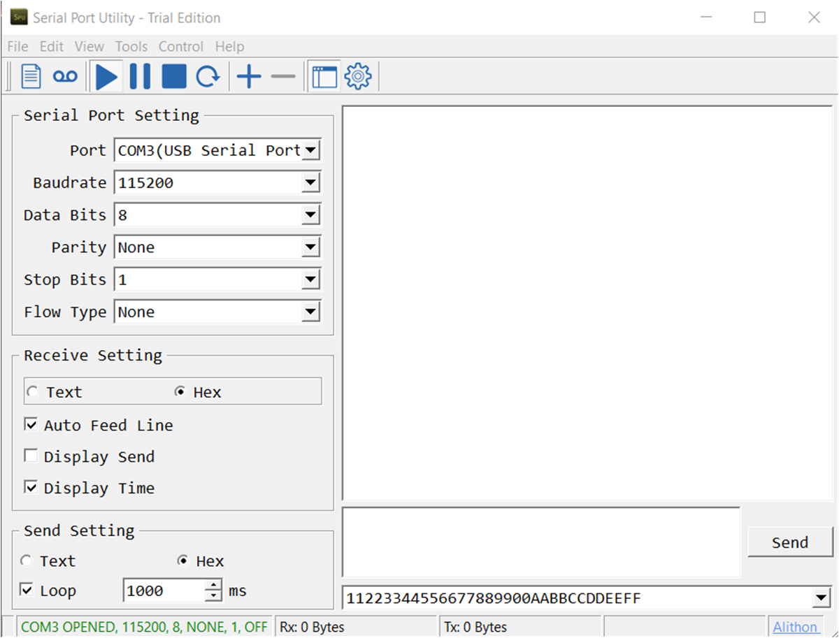
Communication data is generated by a third-party software (Serial Port Utility), which follows the UART protocol with a baud rate of 115200. As shown in Figure 2-2, a string 11223344556677889900AABBCCDDEEFF in hexadecimal (hex) format has been chosen to be transmitted as shown. The same software in a separate graphical user interface (GUI) can be used to check received data. If the computer does not have enough serial communication ports (COM) to check signal at 4 nodes simultaneously, a 1 to 4 USB hub and 4 TTL-232R cables from Future Technology Devices International Ltd. can be used. Therefore, one physical port is occupied, while 4 virtual ports are created by the operating system.
 Figure 2-2 Serial Communication Software
GUI
Figure 2-2 Serial Communication Software
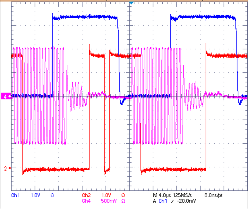
GUIOne node is set as the transmitter by setting the mode pin (pin 2) high (Node 1 in Figure 2-1), while the other three are set as receiver. In this bench test, waveforms are captured at Node 1 and Node 3. In the snapshot of Figure 2-3, channel 1 is the transmitting signal of the D pin (pin 4) of Node 1, while channel 4 is the differential bus signal near the bus pins (pin 6 and pin 7) of Node 3. The bus signal has several toggling waveforms with small amplitude after the 0-to-1 transition, which is due to the reflection generated by long stubs and open ends. Channel 2 is the receiver output (pin 1) of Node 3. Because of the disturbed bus signal, the receiver generates 0 when it is supposed to stay as 1. This kind of signal integrity issue can be problematic in applications due to high error bit rate in communication.
 Figure 2-3 Waveforms of 4-node star
network