SLLA574 March 2022 THVD1406 , THVD1426
2.3 Test Three: A System With No Termination
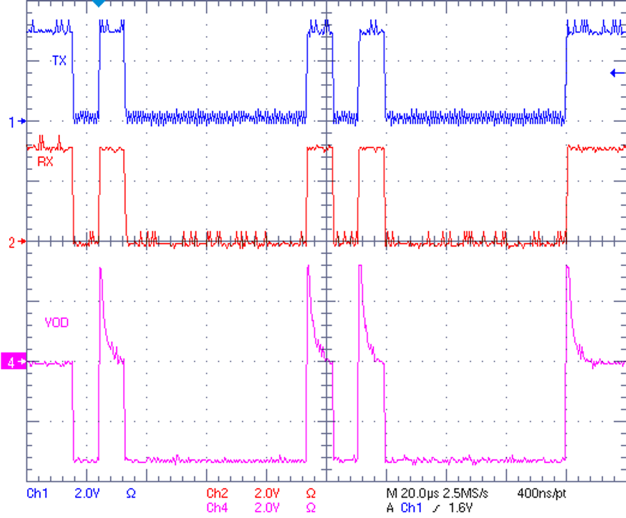
The third test follows the same procedure with the same data rate except the board is no longer terminated. In some applications where the data rate is low and the distance is short, the signal integrity can still be within acceptable margins without termination in the system. Other than saving power, sparing termination also makes implementation easier since all nodes can be treated equally. It is observed from the results as shown in Figure 2-4 that the bus amplitude is larger due to lighter bus load, while the bus discharge time is much longer than what is observed in the second test. The reason is that the bus impedance is much higher than 120-Ω when the termination is removed. Therefore, the RC decay with the disabled driver is much larger. Please note that the different discharge time does not affect the communication. Of course, results can vary if the bus load is larger or data rate is faster.
 Figure 2-4 Auto Direction Test of
THVD1426 with Low Data Rate and No Termination