SLLA574 March 2022 THVD1406 , THVD1426
2.4 Test Four: A System With a Fully Loaded Bus
Based on these two previous tests, two EVMs and 300-ft AWG 22 cables are used to test long-distance communication with the same low baud rate 115200. As before, the SHDN pin (pin 2) is set to a logic high and the REB pin (pin 3) set to a logic low on both the leader and follower nodes. In this test, the data is transmitted by the leader node at the D pin and is received by the follower node at the R pin. Generally, in systems with long cables, the transmission line effects need to be considered. Termination resistors are always recommended on boards for better signal integrity. This test is no exception. To mimic the load of multiple nodes, 375-Ω resistors are inserted from the bus to ground as shown in Figure 2-5. In the real world, the common mode node of the load could have some potential shift other than ground. Each input of THVD14x6 has about 96-kΩ impedance. The 375-Ω lumped resistor represents about 256 nodes.
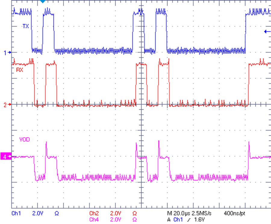
In the waveforms of Figure 2-6, TX (channel 1) is the input at the D pin of the leader node, the receiver output waveform (channel 2) and bus signal waveform (channel 4) are taken on the board of the follower node. The measured results show that bus signal is attenuated due to cable loss, while the shape of bus signal is kept similar to the one shown in Figure 2-5. Like the results of the second test, no issues were found in the communication. The same comments also apply to this setup - adding some bus bias network would make the communication more robust.
 Figure 2-6 Test Results of 115.2-kbps
300-ft Transmission with a Fully Loaded Bus