SLLA595C march 2023 – june 2023 THVD1424 , THVD1454
- Abstract
- 2
- Trademarks
- 1Typical RS-485 Networks and the Need for Termination
- 2Network Length, Data Rate, and Stubs
- 3Discrete Design for Switchable Termination and Duplex Switching
- 4Discrete Design for Duplex Switching
- 5 THVD1424 and THVD1454 Flexible RS-485
- 6Application Diagrams with THVD1424
- 7Experimental Results from Four Node Testing of THVD1424
- 8Conclusion
- 9Revision History
7 Experimental Results from Four Node Testing of THVD1424
A four-node half-duplex network was constructed using 50 feet twisted pair cabling and four THVD1424 boards connected as shown below. Ideal topology for multi-point network is daisy-chain, however the network built here is bus topology with stubs to show the impact of long stubs deteriorating the signal quality.
 Figure 7-1 Network Set-up with
THVD1424
Figure 7-1 Network Set-up with
THVD1424Each node was connected to 5 V and ground was common between all nodes. Node B was driven using Function generator and bus waveforms were checked on Node A.
Case 1: Slew rate control (SLR) pin for each node was connected to ground to check the impact of termination at high speed. Node B driven at 2 Mbps
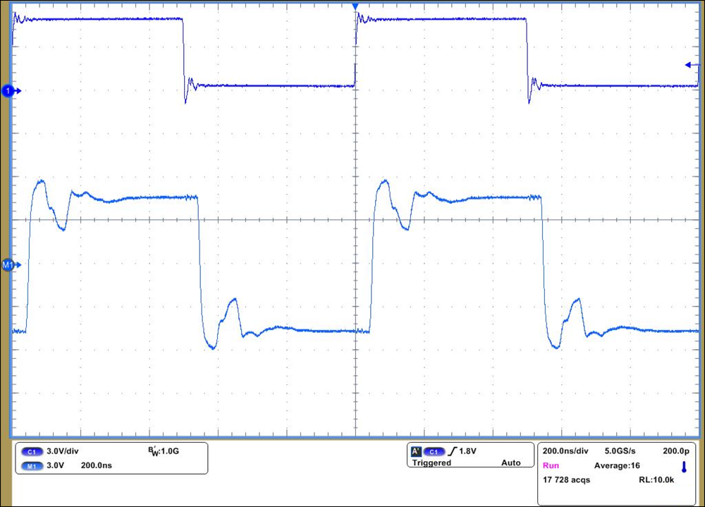 Figure 7-2 Node A and Node D
Un-terminated with Signaling at 2 Mbps
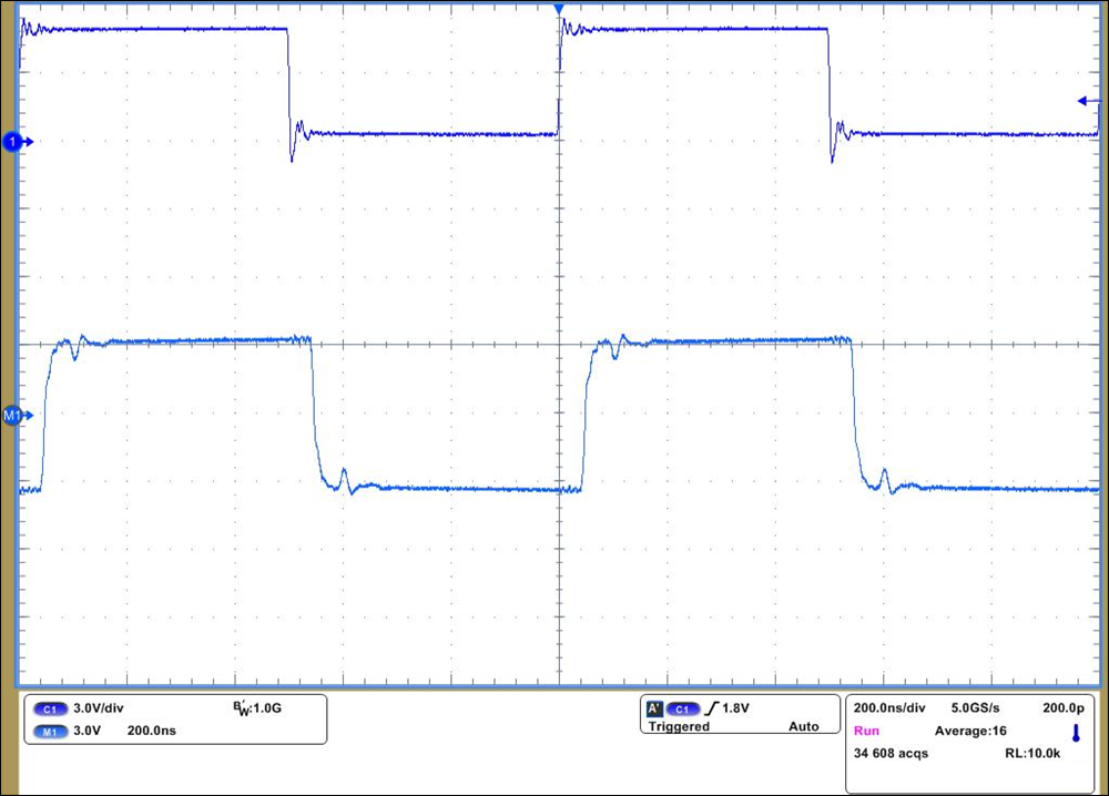 Figure 7-3 Node A and Node D
Terminated with Signaling at 2 Mbps
 Case 2: Node B driven at 10 Mbps
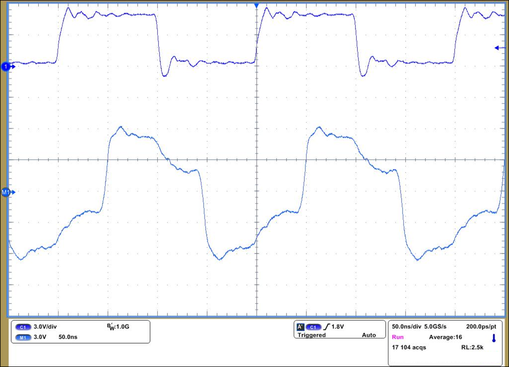 Figure 7-4 Node A and Node D
Un-terminated with Signaling at 10 Mbps
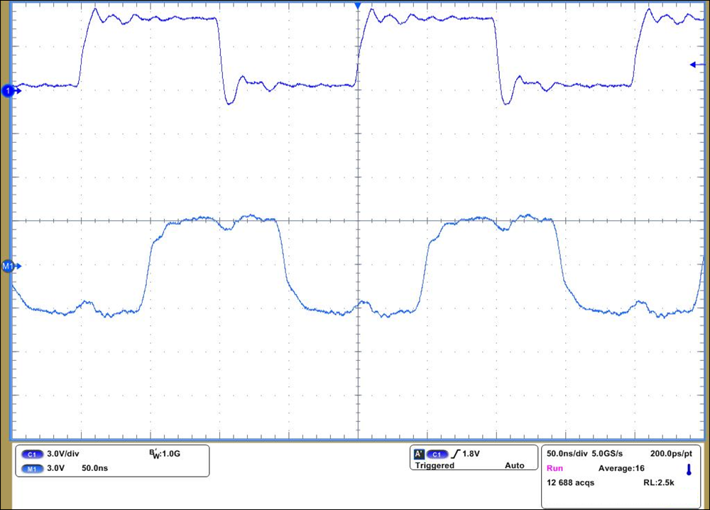 Figure 7-5 Node A and Node D
Terminated with Signaling at 10 Mbps
 Case 3: Node B driven at 20 Mbps
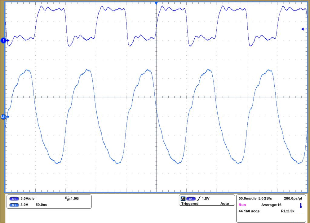 Figure 7-6 Node A and Node D
Un-terminated with Signaling at 20 Mbps
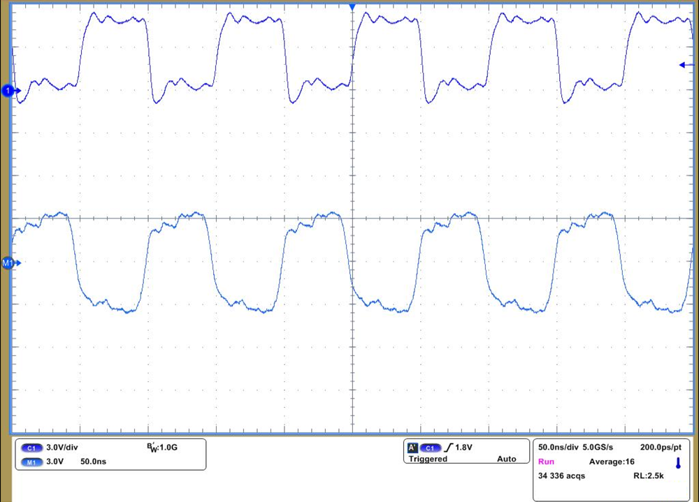 Figure 7-7 Node A and Node D
Terminated with Signaling at 20 Mbps
 Case 4: SLR pin was made High for all nodes and Node B was driven at 500 kbps.
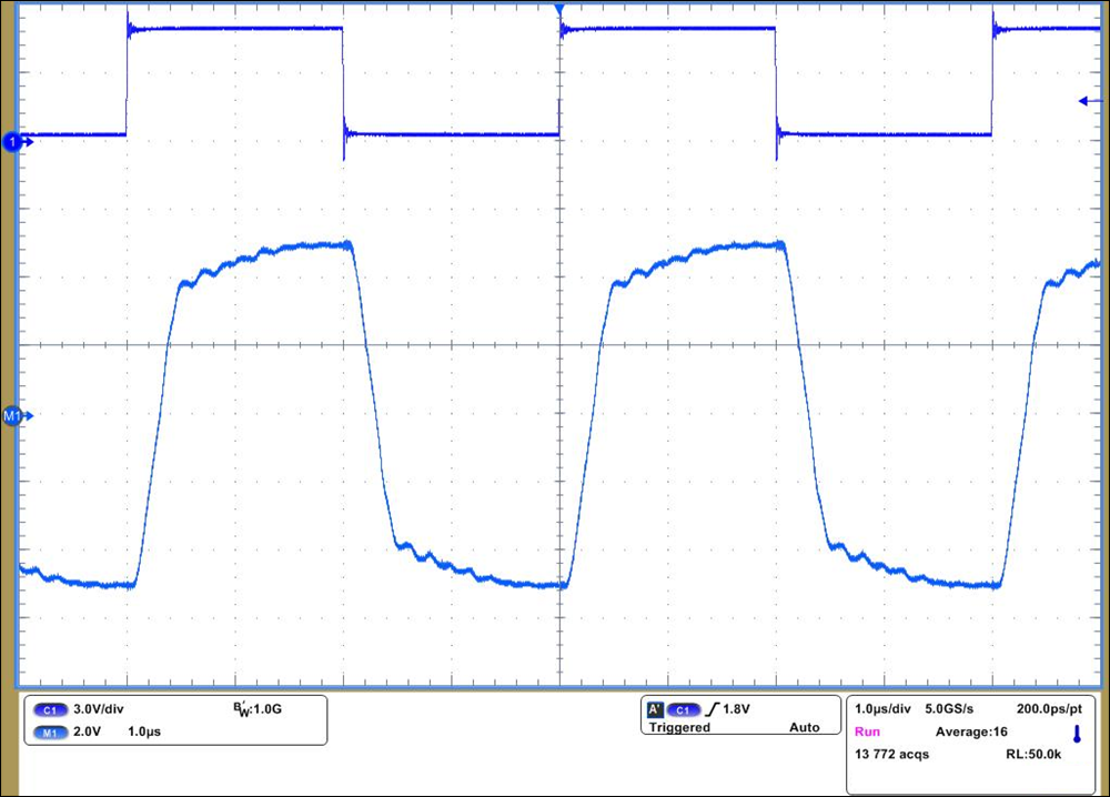 Figure 7-8 Node A and Node D
Un-terminated with Signaling at 500 kbps
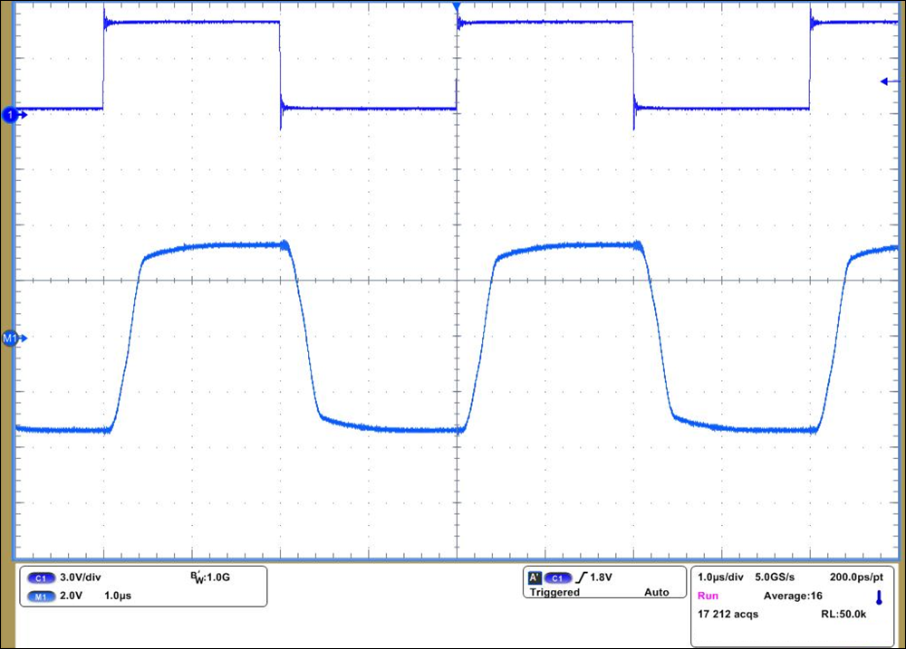 Figure 7-9 Node A and Node D
Terminated with Signaling at 500 kbps
 As shown from above waveforms, having both ends of the network terminated substantially improves the bus waveforms by reducing reflections. Even though 500 kbps is much slower speed and termination becomes optional at low speeds and at this distance, presence of termination still improves bus waveforms.
Please note: Terminated bus waveforms have smaller amplitude which is expected because unloaded driver differential output swings closer to supply and hence is larger than loaded driver output. Also stub length is intentionally kept longer than what would be encountered in actual networks for these transition times (~10 ns typical for driver set in 20-Mbps mode). Another note is 50-feet network length for 20 Mbps signaling rate will perform slightly worse due to AC losses of the cable, hence the waveforms even under terminated conditions are not ideal.