SLLA595C march 2023 – june 2023 THVD1424 , THVD1454
- Abstract
- 2
- Trademarks
- 1Typical RS-485 Networks and the Need for Termination
- 2Network Length, Data Rate, and Stubs
- 3Discrete Design for Switchable Termination and Duplex Switching
- 4Discrete Design for Duplex Switching
- 5 THVD1424 and THVD1454 Flexible RS-485
- 6Application Diagrams with THVD1424
- 7Experimental Results from Four Node Testing of THVD1424
- 8Conclusion
- 9Revision History
2 Network Length, Data Rate, and Stubs
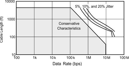
RS-485 standard provides guideline for selecting maximum operational data rate and network length as shown in Figure 2-1.
 Figure 2-1 Cable Length vs Data Rate
Characteristics
 Figure 2-1 shows the inverse relationship between signaling rate and cable length corresponding to the tolerable jitter. Solid line is a conservative estimate with almost no jitter. Network length can be extended if the system is able to tolerate higher jitter in the signal (5%, 10%, and 20% jitter curves in the diagram) while still able to distinguish high and low bits properly. At lower data rates, DC resistance of the cable limits the maximum communication distance since cable resistance attenuates the signal. As the frequency of the signal increases, AC properties of the cable and rise/fall time of the driver starts limiting the network performance of speed vs distance.
Once the network length and operational data rate for an RS-485 network is decided, next task is to decide the maximum stub length to maintain good signal quality. As a general conservative guideline, the electrical length, or round-trip delay, of a stub is recommended to be less than one-tenth of the rise time of the driver, thus giving a maximum physical stub length as shown in Equation 2.
where
- tr is the 10/90 rise time of the driver
- c is the speed of light (3 × 10⁸ m/s)
- v is the signal velocity of the cable or trace as a factor of c
- v is the signal velocity of the cable or trace as a factor of c
This leads to the fourth problem for system designers – to select different devices for their slow or fast speed network designs.