SLLA618 October 2023 ATL431 , ATL431LI , TL431 , TL431LI , TLVH432
4 Methodology
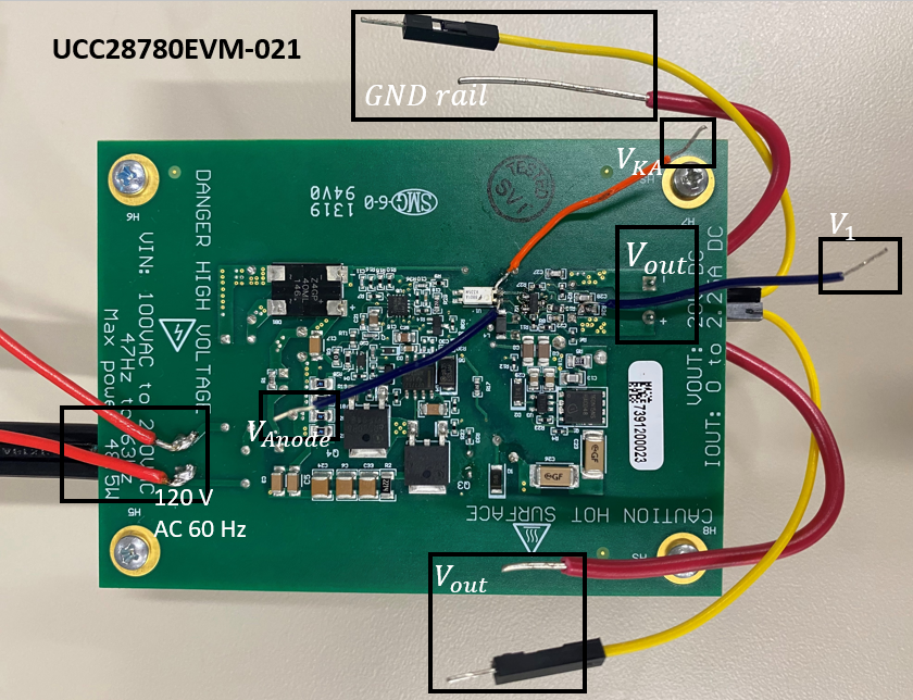
To prove the performance improvements of some shunt references over others, the TL431, TLVH432, ATL431, TL431LI, and ATL431LI were all separately tested with their own required bias currents on the UCC28780EVM-021, which is a flyback EVM (Evaluation Module) with SSR. This flyback EVM uses the biasing topology shown in Figure 2-4. This experiment connected an E-load to the flyback output to test each shunt reference under a no-load condition (standby mode), a 20-W load, and a 40W load. The EVM was powered with an isolated 120 V 60 Hz source via an isolation transformer and a virac. The biasing resistance was determined by following the steps in Section 2.2, where this resistance set Ibias = IKA(min) under a 40W load. Several test points were soldered onto the EVM to properly analyze the results to determine the optocoupler diode feedback current, IFB(secondary), the biasing current, Ibias, and the output voltage, Vout. This test setup is shown in Figure 4-1, which shows the actual EVM being tested, and in Figure 4-2, which shows the full feedback network, including the test points and compensation capacitors.
 Figure 4-1 EVM Test Board Setup
 Figure 4-2 Control Network Probe Connections