SLLA618 October 2023 ATL431 , ATL431LI , TL431 , TL431LI , TLVH432
4.4 Transient Response Comparison
The transient response of each shunt reference was observed by switching a 40 W load on and off while observing the instantaneous reactions of the output voltage, Vout, and the feedback current, IFB(secondary). When an electrical load is applied, the output voltage can suddenly drop due to voltage losses caused by the current flow through the flyback converter. The larger the load applied, the larger the voltage losses. A sudden drop in the output voltage results in a drop in the reference voltage, thus decreasing the cathode current, IKA, being shunted through the shunt reference. This reduced current flow decreases the feedback current through the optocoupler, IFB(secondary), thus decreasing the signal being received by the PWM controller. Some shunt references had a quicker transient response than others due to the gain of these shunt references, which isn't provided in any of these devices' data sheets. The following images show the observed transient response for each shunt reference.
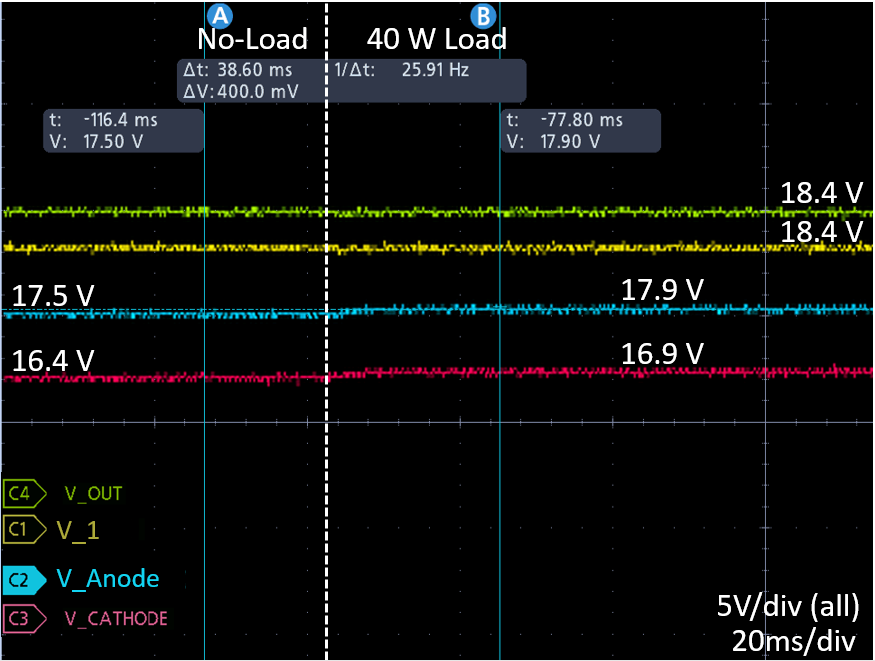 Figure 4-18 TL431 Transient Response
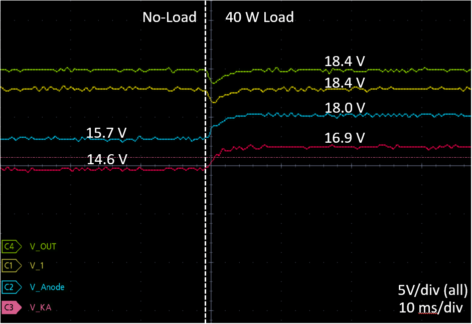 Figure 4-20 ATL431 Transient Response
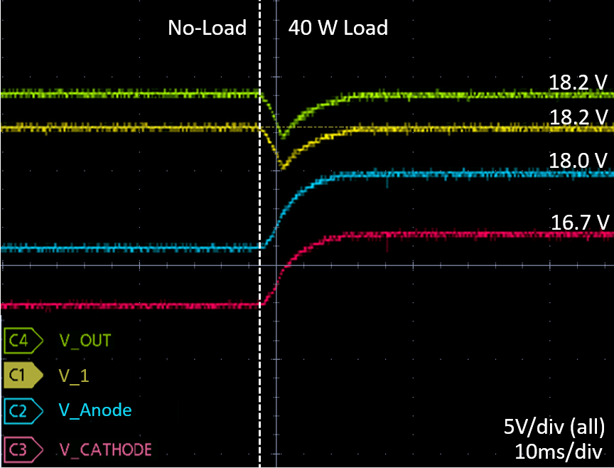 Figure 4-22 ATL431LI Transient Response
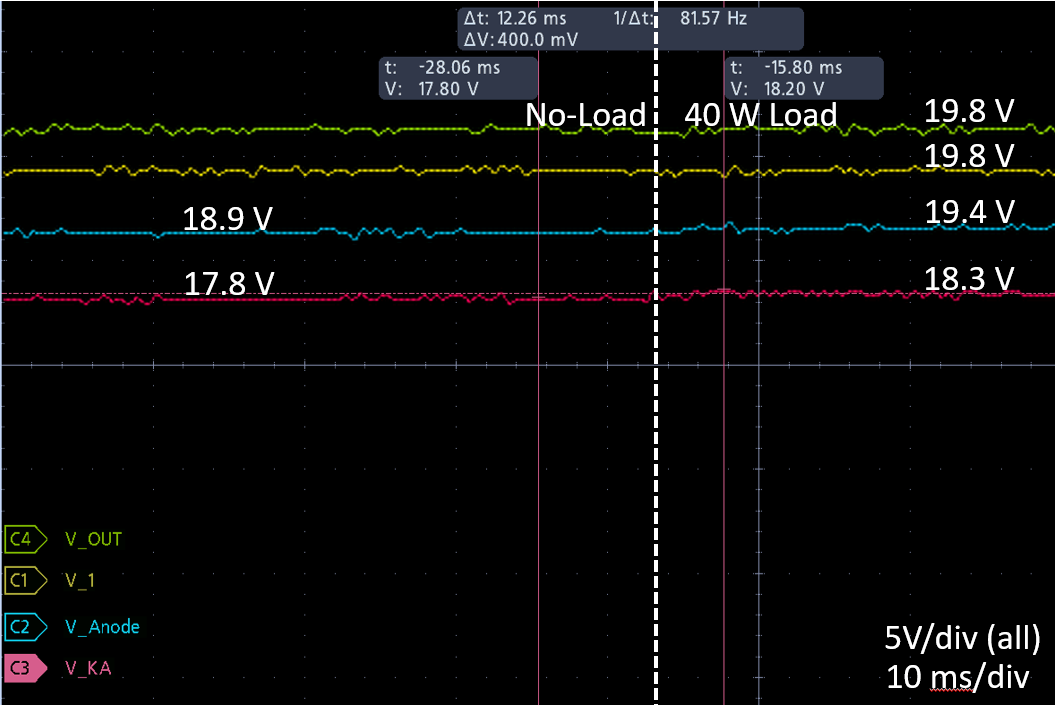 Figure 4-19 TLVH432 Transient Response
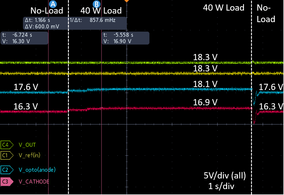 Figure 4-21 TL431LI Transient Response
These plots show the transient response of each shunt reference when a 40 W load is switched on. The TL431/LI and the TLVH432 performed well, with no noticeable change in the output voltage, while the ATL431/LI performed noticeably slower. The ATL431/LI's cathode voltage, VKA, and anode voltage, VAnode, fall significantly below their steady-state values once a load is turned off and then take considerable time to stabilize. While this does not impact the accuracy of the flyback output voltage, the time increased for their transient responses to occur and resulted in extra power dissipation while these voltages were steadying out. The scope shots for the ATL431/LI in Figure 4-20 and Figure 4-22 , both show the transient response of switching a 40 W load on shortly after that same load was switched off.