SLLA628 September 2023 THVD1424
- 1
- Abstract
- Trademarks
- 1Use Case Domain of RS-485
- 2Traditional RS-485 Design Process
- 3One Multi-System Design: Flexible RS-485 with the THVD1424
- 4Summary
- 5References
1.2 RS-485 Compliant Receiver
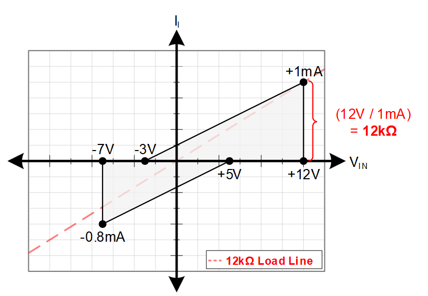
An RS-485 compliant receiver also includes a few key requirements to be compliant with the standard. The first of which is a -7 V to 12 V common mode input voltage range – like the transmitter specification it can be greater than this range but not less. Next, the receiver’s sensitivity is defined through the positive going threshold (value to switch from a logic 0 to a logic 1) denoted as VIT+ and the negative going threshold (value to switch from a logic 1 to a logic 0) denoted by VIT- , which require that a logic 1 is guaranteed at a differential input of 200mV and above and a logic 0 is guaranteed at a differential input of -200 mV and below. It should be noted that many different possible combinations can exist for threshold values within the window defined by standard. Finally, we have the bus input current, denoted Ib, which is used to determine loading of the RS-485 bus; an RS-485 receiver has a maximum loading of 1 Unit load.
 Figure 1-1 Standard Unit Load Chart for
RS-485 Compliant Receivers
Figure 1-1 Standard Unit Load Chart for
RS-485 Compliant ReceiversThe standard allows 32 unit load devices on one bus – devices can also have fractional unit loads, such as 1/8th unit load, to allow for more devices on a bus.