SLLA628 September 2023 THVD1424
- 1
- Abstract
- Trademarks
- 1Use Case Domain of RS-485
- 2Traditional RS-485 Design Process
- 3One Multi-System Design: Flexible RS-485 with the THVD1424
- 4Summary
- 5References
2.2.3 Max Bus Length, Network Topology, Emission Concerns, and Data Rate Required
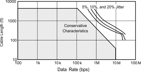
Next a designer must consider the required data rate of the system and how that impacts what the max bus length, network topology selected, and emissions generations. Traditionally RS-485 ran between 0kbps to 10Mbps, but recent developments have some parts push up to 50Mbps. However, there exists a tradeoff between speed and maximum bus length.
 Figure 2-1 Typical RS-485 Cable Length v.
Data Rate Performance
Figure 2-1 Typical RS-485 Cable Length v.
Data Rate PerformanceThe designer must determine what is the minimum required speed and whether the bus length will allow for that speed – in certain cases the addition of RS-485 repeaters may be needed to overcome this limitation. To further complicate the trade-off is the question of network topology. In RS-485 only 2 nodes are terminated – so any additional node is connected to the main trunk of the bus via an unterminated stub. These stubs will act as parallel transmission lines to the main bus if they become too long relative to the transition time of the differential signal – where the maximum stub length allowed to mitigate these effects is effected by the rise time of the transceiver and the signal propagation velocity through the transmission medium.
Daisy Chained systems will minimize the stub lengths to avoid these issues and is why it is the preferred method; however, not all applications can support daisy chaining so the unterminated stub length needs to be considered when selecting a topology. In general, the faster the device the shorter the maximum unterminated stub length can be. This also is the time for the designer to consider emissions concerns, while RS-485 is an EMC friendly interface standard due to the balanced signaling, higher speed devices will increase the high frequency energy content of the signal which are more prone to causing emissions and EMI. Some RS-485 designs will need to add additional EMI protections for an added layer of robustness.