SLLA641 July 2024 TAA5212 , TAC5112 , TAC5212
3.1.2 Test Case 2: Microphone Maximum Input Level
From the microphone Sensitivity of -42dBV and AOP of 110dBSPL given by the manufacturer, the largest input level the microphone can record is -26dBV which is equivalent to 50mVrms single-ended.
AOP is the maximum sound level pressure (SPL) a microphone can handle before the AOP starts to distort the audio signal. This AOP is defined as SPL that causes 10% THD in the microphone's output at 1KHz frequency. A higher AOP is desirable as it allows the microphone to record loud sounds without distortion. Dynamic microphone has a higher AOP than the Condenser microphone, but lower sensitivity level. In this application notes, we are using the AOP for the maximum test case.
A 1KHz tone with 50 mVrms is applied to the analog differential inputs of the device under test (DUT) with 0dB gain setting and the digital output is captured with Audio Precision APx555. The following are the results taken on these two devices.
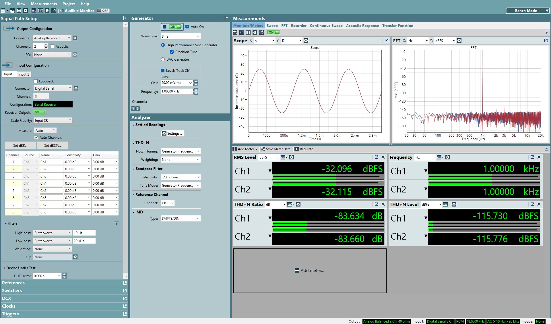
 Figure 3-5 TAA5212 Captured of Maximum mic Input
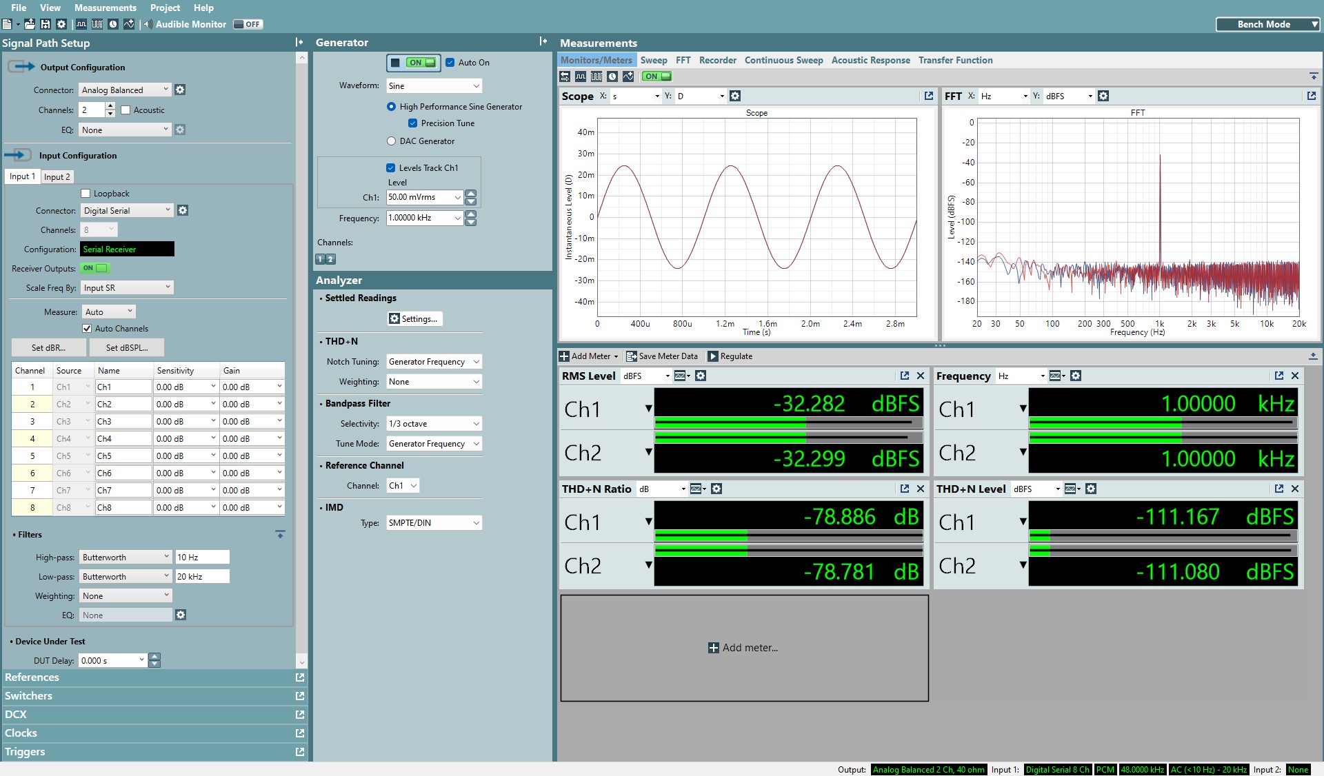
 Figure 3-6 ADC6120 Captured of Maximum mic Input With DRE Disable
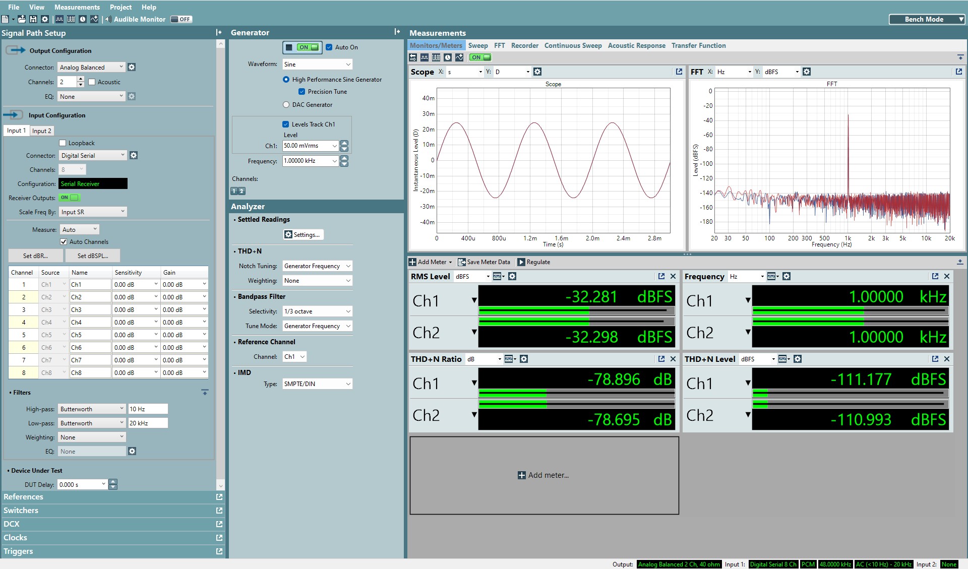
 Figure 3-7 ADC6120 Captured of Maximum mic Input With DRE Enable
Here we can see the recorded input level of the microphone maximum level is -32dBFS for differential configuration from the converter full-scale. Based on the un-weighted Dynamic Range (DR) of the converter, the THDN is calculated by Equation 1 and summarized in Table 3-6 for these devices.
| Analog Input Vrms [dBr(2Vrms)] | Spec DR A-Weighted (dB) | Measured DR Un-Weighted (dB) | Calculated THDN Ratio (dB) | Measured THDN Ratio (dB) | |
|---|---|---|---|---|---|
| TAx5xxx | 50mV [-32dBr] | 118 | 116 | -84 | -84 |
| ADC6120 | 50mV [-32dBr] | 113 | 111 | -79 | -79 |
| ADC6120-DRE | 50mV [-32dBr] | 113(1) | 111 | -79 | -79 |